
A method of sending mipi module single picture control code
A technology for screen control and code control, which is applied to cathode ray tube indicators, instruments, static indicators, etc., can solve the problems of frequently modifying single-chip computer programs, and achieve the effect of reducing the number of single-chip computer program codes, reducing the number of versions, and facilitating management
- Summary
- Abstract
- Description
- Claims
- Application Information
AI Technical Summary
Problems solved by technology
Method used
Image

Examples
Embodiment
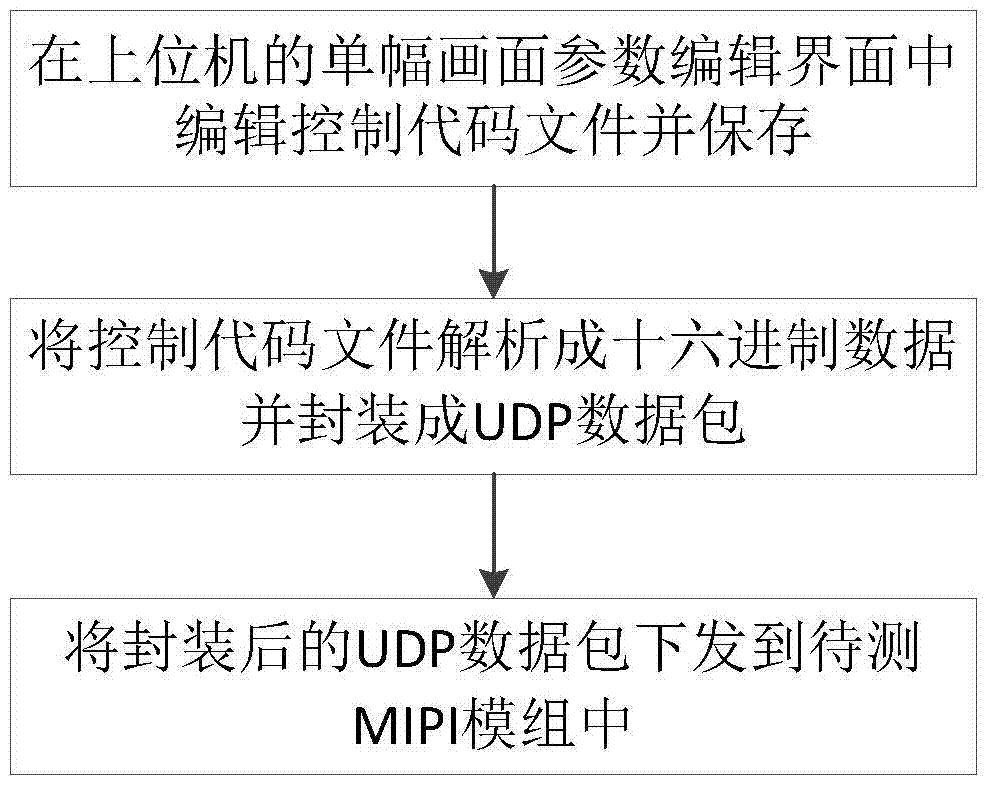
[0034] Example: convert the power supply information "RBA 05 C0 E0 62 D3 81 35 3C 01 06, Delay100ms" of a single frame into hexadecimal data that can be recognized by the single-chip microcomputer in the image signal generator: convert "RBA 05 C0 E0 62D3 81 35 3C 01 06" is converted into "0x39 0xBA 0x0A 0x05 0xC0 0xE0 0x62 0xD3 0x81 0x350x3C 0x01 0x06", "0x39" tells the MCU what type of instruction to issue parameters, 0xBA is the register address, 0x0A is the length of the data behind, The next 10 bytes are the data content; convert "Delay 100ms" to "0x000x00 0x02 0x64 0x00", "0x00 0x00 0x02" tells the MCU to perform the delay operation, and the following bytes indicate the delay time.
[0035] In the above scheme, the protocol used to encapsulate the hexadecimal data into a UDP packet is defined as follows: the first 2 bytes of the protocol are protocol command words 0x02, 0x50, the 3rd byte and the 4th byte is the length of the data packet, the 5th byte and the 6th byte are...
PUM
 Abstract
Description
Claims
Application Information