
A melt for DC fuse link
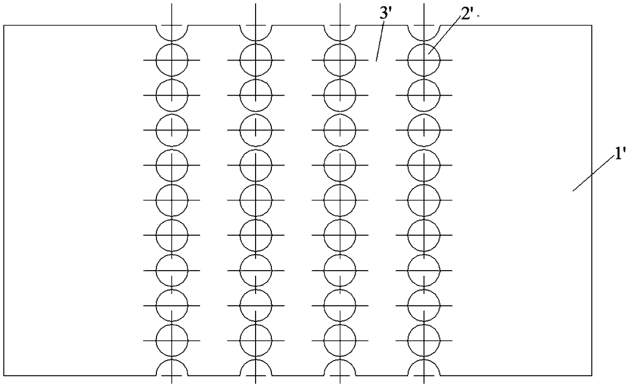
A technology of fuses and melts, which is applied in the direction of emergency protection devices, circuits, electrical components, etc., can solve the problems of slow fusing speed, poor cut-off performance, long fuse time, etc. Effect of temperature rise and heat dissipation improvement
- Summary
- Abstract
- Description
- Claims
- Application Information
AI Technical Summary
Problems solved by technology
Method used
Image

Examples
Embodiment Construction
[0023] In order to enable those skilled in the art to better understand the technical solution of the present invention, its specific implementation will be described in detail below in conjunction with the accompanying drawings:
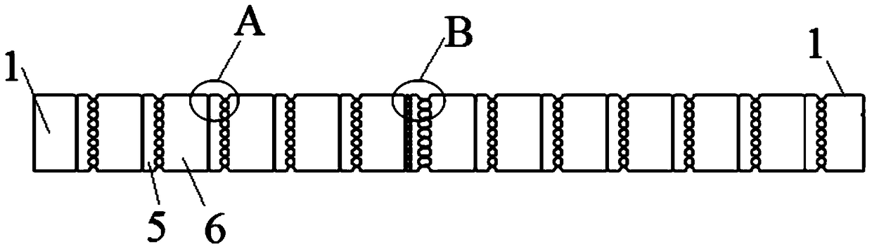
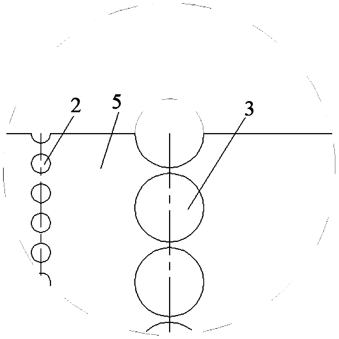
[0024] see figure 2 , image 3 and Figure 4 , the best embodiment of the present invention, a melt for DC fuses, comprising two melt bodies 1, each melt body 1 is provided with a series of first holes 2 and a series of second holes 3, The size of the first hole 2 is smaller than the size of the second hole 3, the first hole 2 is circular, the second hole 3 is circular, and the aperture of the first hole 2 is smaller than the aperture of the second hole 3; The second hole 3 of the series is distributed on the corresponding melt body 1 at intervals from left to right; the two melt bodies 1 are connected in a partially overlapping manner, and the overlap of the two melt bodies 1 is distributed from left to right. There is a row of first holes 2 an...
PUM
 Abstract
Description
Claims
Application Information