Discharge Reactor for Surface Modification of Polymer Materials

A polymer material and surface modification technology, which is applied in the field of polymer material surface modification discharge reactor, can solve the problems of sparks, uneven modification treatment, etc., and achieve the effect of uniform modification treatment

Active Publication Date: 2019-04-05
SUZHOU DINGDEDIAN ENVIRONMENTAL PROTECTION TECH
View PDF3 Cites 0 Cited by
  • Summary
  • Abstract
  • Description
  • Claims
  • Application Information

AI Technical Summary

Problems solved by technology

[0005] The technical problem to be solved by the present invention is to provide a discharge reactor for surface modification of polymer materials, which has The advantages of uniform modification treatment, no sparks and ozone

Method used


Image

  • Discharge Reactor for Surface Modification of Polymer Materials
  • Discharge Reactor for Surface Modification of Polymer Materials
  • Discharge Reactor for Surface Modification of Polymer Materials

Examples


Embodiment 1

[0027] The structure of the polymer material surface modification discharge reactor of the present embodiment is as follows:

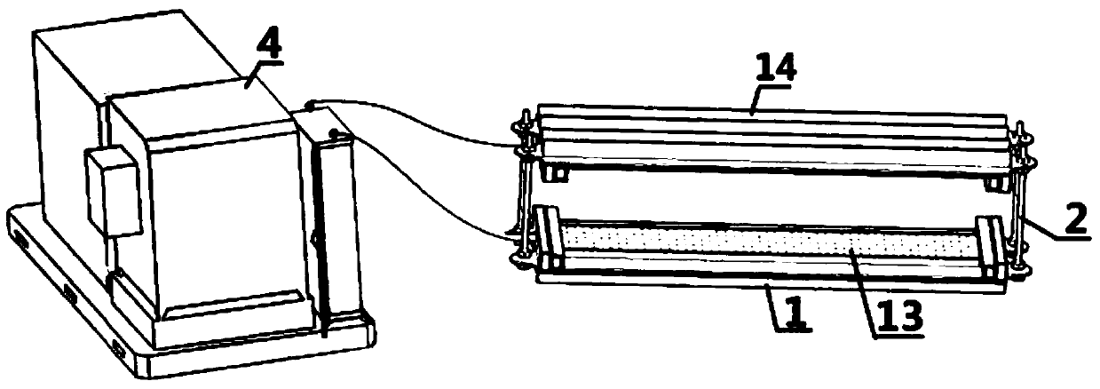
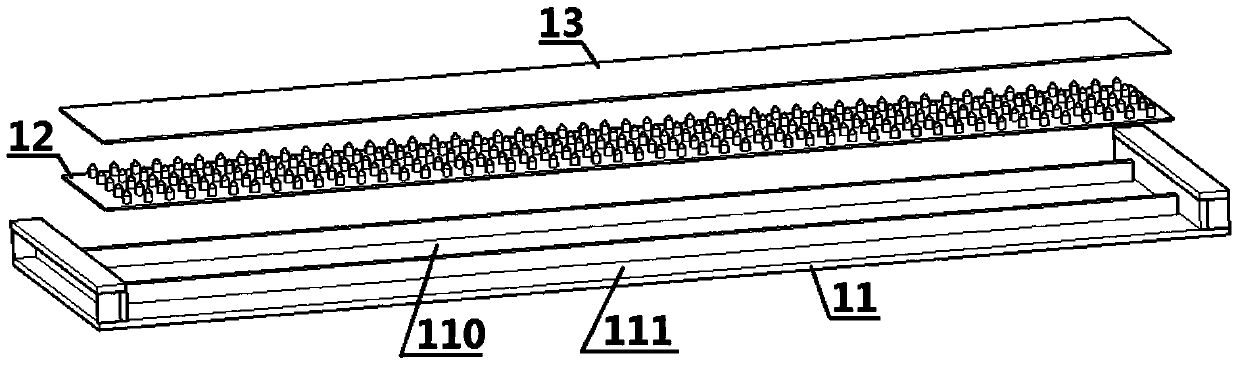
[0028] Please combine Figure 1-2 It should be understood that the discharge reactor for surface modification of polymer materials in this embodiment is used for modifying the surface of polymer materials, and it includes four adjustment screws 2 and two plate-shaped discharge components 1. These adjustment The screw 2 is penetrated and fixed on the four ends of the discharge parts 1, each discharge part 1 includes an insulating shell 11 with a groove 110, a PCB discharge plate 12 uniformly distributed with discharge needles and a catalyst carrier 13. The PCB discharge plates 12 are set in the grooves 110, the catalyst carriers 13 are embedded in the mouths of the grooves 110 and potted with flame-retardant epoxy resin, and the catalyst carriers 13 are parallel to And oppositely arranged, the discharge needles are used to excite the catalyst carriers ...

Embodiment 2

[0040] The structure of the polymer material surface modification discharge reactor of the present embodiment is as follows:

[0041] Please combine image 3 It should be understood that the discharge reactor for surface modification of polymer materials in this embodiment has many similarities with the discharge reactor for surface modification of polymer materials in Example 1, and these similarities will not be repeated here.

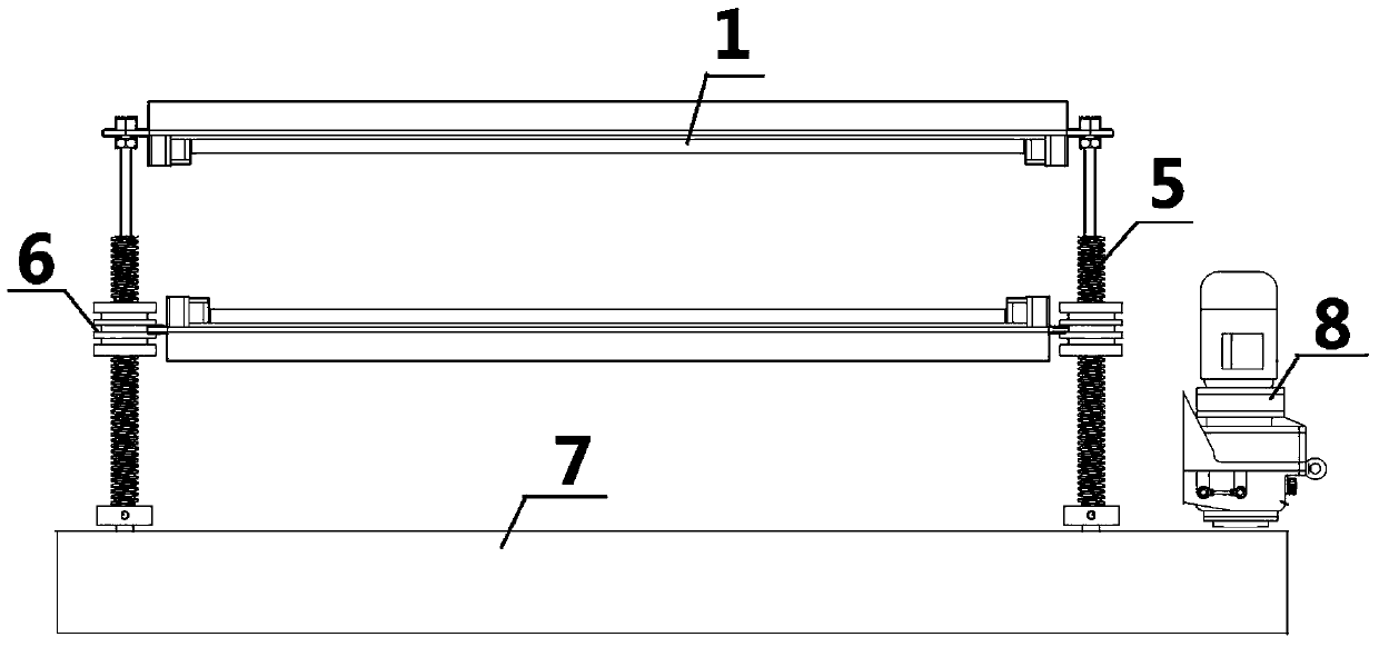
[0042] Please combine image 3It should be understood that the polymer material surface modification discharge reactor of the present embodiment also includes a motor 8 and a synchronous driving device 7, and the adjusting screws 5 each have a pivot portion and a screw rod portion, and the discharge components One discharge part in 1 is pivotally connected to these pivot parts, the other discharge part in these discharge parts 1 is pivotally connected to these screw rod parts, and the motor 8 is used to drive these adjustments through the synchronou...


PUM


Abstract

A discharge reactor for surface modification of macromolecular material. The discharge reactor comprises four adjustment screw rods (2) and two panel discharge elements (1). The adjustment screw rods (2) penetrate and are fastened on the four ends of the discharge elements (1). Each discharge element (1) comprises an insulating casing (11) having a slot (110), a PCB discharge board (12) evenly distributed with discharge needles, and a catalyst carrier (13). The PCB discharge boards (12) are provided in the slots (110). The catalyst carriers (13) are embedded at the opening of the slots (110), and are sealed by flame-retardant epoxy resin. The catalyst carriers (13) are arranged in parallel and opposite to one another. The discharge needles are used to excite the catalyst carriers (13) to discharge, such that ions for bombarding the macromolecular material surface are formed between the catalyst carriers (13).

Description

technical field [0001] The invention relates to the field of polymer material surface modification processing, in particular to a polymer material surface modification discharge reactor. Background technique [0002] Polymer materials include rubber, plastics, fibers, coatings, adhesives and polymer-based composite materials. They are the products of modern high technology and are widely used in people's daily life. During the application process, it is found that polymer materials have some The characteristics are not conducive to application or processing, such as water repellency, difficult sticking, difficult printing, difficult dyeing and other problems. [0003] In order to solve the above technical problems, researchers in the printing field have proposed two methods: dry modification and wet modification, among which dry modification is more common, and generally include discharge treatment, flame treatment, ozone treatment and other processing methods. [0004] How...

Claims


Application Information

Patent Timeline
Patent Type & Authority Patents(China)
IPC IPC(8): B01J19/08
CPCB01J19/08
Inventor 洪昆喨
Owner SUZHOU DINGDEDIAN ENVIRONMENTAL PROTECTION TECH
Why Eureka
Try Eureka