fast sampler

A sampler and fast technology, applied in the field of boilers, can solve problems such as user experience to be improved and troublesome, and achieve the effect of improving user experience, high efficiency, and convenient processing and manufacturing

Inactive Publication Date: 2017-11-21
山东亿泰粮油食品有限公司
View PDF7 Cites 0 Cited by
  • Summary
  • Abstract
  • Description
  • Claims
  • Application Information

AI Technical Summary

Problems solved by technology

The above two sampling methods may be troublesome, and the user experience needs to be improved

Method used


Image

  • fast sampler
  • fast sampler
  • fast sampler

Examples


Embodiment 1

[0051] In order to distinguish the head and the tail of the parts, the part close to the handle 204 is called the tail, and the part far away from the handle 204 is called the head.

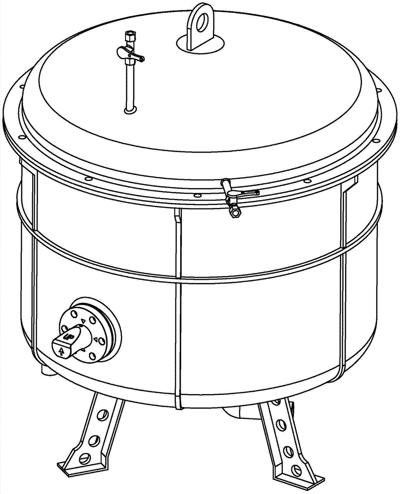
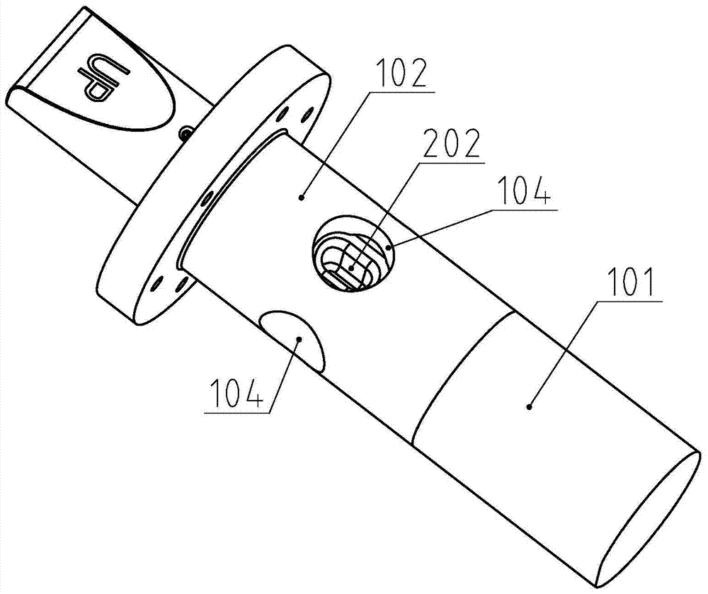
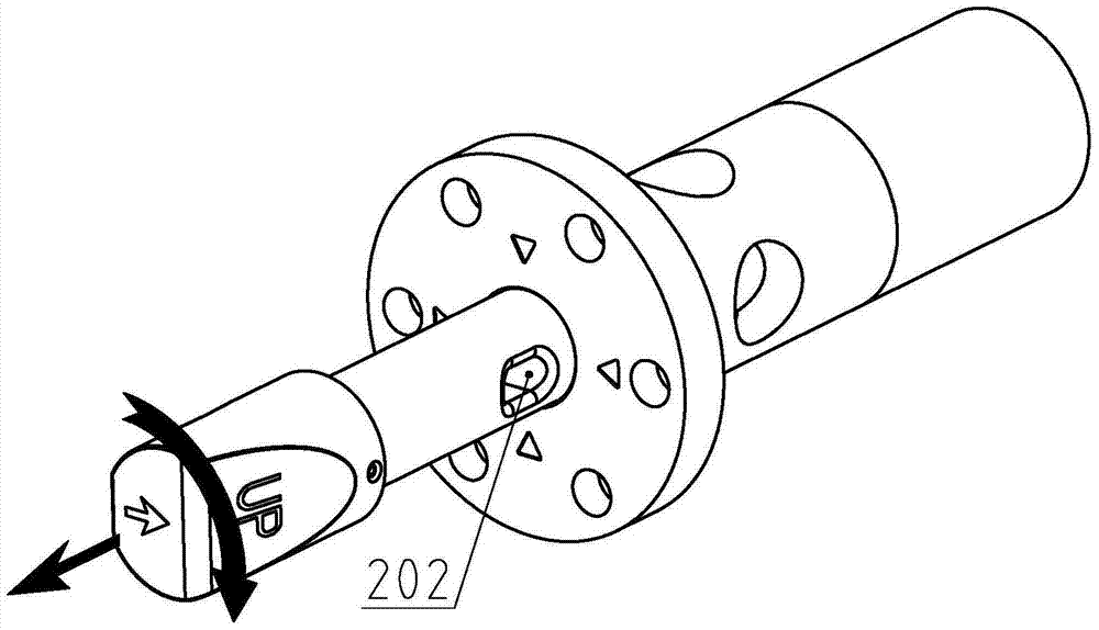
[0052] Such as figure 1 As shown, a sampler is installed near the bottom of the side wall of the boiler, and the sampling rod 2 is in the insertion position. When it is necessary to sample the liquid in the boiler, the sampling rod 2 only needs to be pulled out, and the sampling hole on the sampling rod 2 is 202 is fully exposed, that is, the sampling rod 2 is in the pulled out position (see Figure 7 ), turn the sampling rod 2 (see image 3 with 8 ), that is, the liquid in the sampling hole 202 is poured into the container, and then the sampling rod 2 is rotated and pushed back to the insertion position. The sampling process only needs three actions, one pull, one turn and one push, which is convenient and fast, with less actions, short time and high sampling efficiency.

[0053] Such as f...

Embodiment 2

[0079] Such as Figure 14-16 As shown, the limiter 3 is provided with two limit pins 301 and one extension spring 302, the extension spring 302 and the limit pin 301 are coaxially arranged, the two limit pins 301 are placed oppositely, and the extension spring 302 makes The shoulder end surface 303 of the limiting pin 301 cooperates with the outer cylindrical surface of the sampling rod 2 , and the shoulder cylindrical surface 304 of the limiting pin 301 cooperates with the stepped surface 111 of the base 102 . Such setting realizes the friendliness of assembly. First, turn the two mounting holes at the head end of the sampling rod 2 to a horizontal position, and then conveniently install the two limit pins 301 from the outer cylindrical surface of the sampling rod 2 into corresponding positions. Then one end of the extension spring 302 is hooked to the stop pin 301, and then the extension spring 302 is elongated by a certain amount and hooked to another stop pin 301. After as...

Embodiment 3

[0081] Such as Figure 12 As shown, the number of the second through holes 104 of the base 102 in the first embodiment is set to 1, and the diameter of the second through holes 104 is larger than the diameter of the first through holes 103. A certain space is formed on both sides, and such a space serves as a flow area 111 , which facilitates the flow of the liquid in the second through hole 104 , thereby renewing the liquid around the sampling hole 202 .


PUM


Abstract

The invention relates to a fast sampler used on a boiler. The fast sampler is provided with a thief rod which is in closed sliding or running fit with a matrix. The matrix is also provided with a cover. The cover and a pedestal are in detachable closed fit. The cover is coaxially provided with a holding cavity for holding the thief rod. When the thief rod is positioned at an insert position, the junction between the cover and the pedestal is positioned between a first groove and a stopper. The head part of the pedestal is provided with a first countersink, diameter of which is greater than diameter of a first through hole. The first countersink and the first through hole form a step surface. The stopper is detachably arranged at the head part of the thief rod. When the stopper matches the step surface of the pedestal, a thief hole is positioned on the outside of the pedestal. By dismounting the matrix into the pedestal and the cover, axial processing length of the pedestal is reduced so as to lower processing difficulty. It is convenient to assemble the stopper by arranging the junction between the first groove and the stopper. By arranging the stopper at the head end of the thief rod, axial dimension of the pedestal and axial dimension of the thief rod are both decreased so as to save materials.

Description

technical field [0001] The invention relates to the field of boilers, in particular to a quick sampler. Background technique [0002] The air pressure in the boiler is usually inconsistent with the air pressure of the outside atmosphere. When it is necessary to detect and analyze the liquid in the boiler, it must be sampled first, so some sampling ports will be set on the boiler. There are two common approaches. 1. Install a ventilation valve on the top of the boiler, and set a sampling valve at the bottom of the boiler. When sampling is required, first open the ventilation valve to make the air pressure inside the boiler equal to the outside air pressure, then open the sampling valve to complete the sampling. 2. Install a pipe with 3 valves on the boiler. The liquid in the pipe and the liquid in the boiler are circulating. First close two of the valves to isolate the liquid between the two valves from the boiler. Sampling is accomplished by opening a third valve between ...

Claims


Application Information

Patent Timeline
Patent Type & Authority Patents(China)
IPC IPC(8): G01N1/10
CPCG01N1/10G01N2001/105
Inventor 龚柱
Owner 山东亿泰粮油食品有限公司
Why Eureka
Try Eureka