Anemorumbometer angle measurement error compensation method based on wind speed influence

An anemometer and angle measurement technology, which is applied in the control of wind turbines, wind power generation, wind turbines, etc., to achieve the effect of improving measurement accuracy and power generation efficiency

Inactive Publication Date: 2016-05-11
DALIAN SHINERGY SCI & TECH DEV
View PDF8 Cites 24 Cited by
  • Summary
  • Abstract
  • Description
  • Claims
  • Application Information

AI Technical Summary

Problems solved by technology

[0011] There is no relevant report on the influence of different wind speeds on the angle measurement error of the anemometer.

Method used


Image

  • Anemorumbometer angle measurement error compensation method based on wind speed influence
  • Anemorumbometer angle measurement error compensation method based on wind speed influence
  • Anemorumbometer angle measurement error compensation method based on wind speed influence

Examples


Embodiment 1

[0050] like Figure 7 As shown, the anemometer has different angle measurement errors at different wind speeds for a fan model. When the wind speed is 4.0m / s, the angle measurement error of the anemometer is -10°; when the wind speed is 6.5m / s , the angle measurement error of the anemometer is 0°; when the wind speed is 9.0m / s, the angle measurement error of the anemometer is 10°.

[0051] according to Figure 10 The process shown, for each wind speed segment V i The angular measurement error of the anemometer under δ i Carrying out the least squares fitting, the angle error compensation function can be obtained as:

[0052] δ=f(v)=4v-36

[0053] This function shows that the relative error of the least square fitting result of n=1 is better than 0.01%, that is, the angle measurement error function is a linear function of wind speed. If at this time the wind direction and anemometer's measured wind direction deviation angle is θ 2 =10°, and the wind speed is v=5m / s, the a...

Embodiment 2

[0055] All wind speed segments V of a certain fan in a wind farm in Hebei i The angle measurement error δ under i To summarize, such as Figure 8 shown, according to Figure 10 The flow shown uses the least squares method to fit it, and then obtains the angle measurement error function as:

[0056] δ=f(v)=0.1v 2 +1.5v-10

[0057] This function shows that in the fitting process, when n=2, the overall relative error of the least square fitting result is better than 0.01%, that is, the angle measurement error function is a quadratic function of wind speed (such as Figure 9 shown).

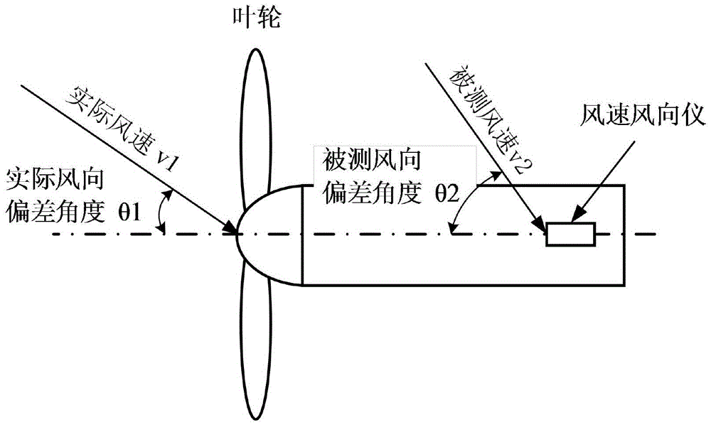
[0058] The anemometer is based on the angle measurement error function δ=f(v) and the wind speed v at the impeller at this time to the wind direction deviation angle θ measured by the anemometer 2 For error compensation, the formula is as follows:

[0059] θ 1 = θ 2 -δ=θ 2 -f(v)

[0060] Then the wind speed and direction instrument will calculate the compensated wind direction deviation an...


PUM


Abstract

The invention discloses an anemorumbometer angle measurement error compensation method based on wind speed influence. The anemorumbometer angle measurement error compensation method comprises the following steps of: carrying out data preprocessing in a learning cycle and forming an angle measurement error function by a least-square fitting method; and applying the angle measurement error function to the angle measurement error compensation of the anemorumbometer in an operation cycle, and sending a compensated wind direction deviation angle theta 1 to a master control system by the anemorumbometer, and causing impellers of a draught fan to directly face the wind direction by the master control system according to the wind direction deviation angle theta 1. The anemorumbometer angle measurement error compensation method has the beneficial effects that as wind direction data measured by the anemorumbometer can be subjected to error compensation in the operation cycle of the draught fan according to the real-time wind speed, the measurement accuracy of wind direction at the impellers of the draught fan is improved, and meanwhile the power generation efficiency of the draught fan is also improved. For example, after the anemorumbometer angle measurement error compensation method is applied to the draught fan in a wind field of Hebei, the mean value of an obtained draught fan angle measurement error curve is about 5 degrees, and further the power generation capacity of the draught fan can be increased by 1.14%.

Description

technical field [0001] The invention relates to an anemometer, in particular to an angle measurement error compensation method of the anemometer. Background technique [0002] Wind turbines convert the kinetic energy of wind into electricity, with the goal of generating as much electricity as possible while keeping the mechanical load on the wind turbine low. To successfully achieve the above goals, the key is to have the fan impeller accurately aligned with the wind direction. [0003] like Figure 1-2 As shown, according to the theory of wind turbine dynamics, when the wind speed is constant and the generator speed is lower than the rated speed, the power generated by the wind turbine is proportional to the cube of the cosine of the wind direction deviation angle θ. Assuming that the wind direction has no deviation, the power obtained by the fan impeller is Power1; when the wind speed is constant and the wind direction deviation angle is θ, the power obtained by the fan i...

Claims


Application Information

Patent Timeline
Patent Type & Authority Applications(China)
IPC IPC(8): F03D7/04
CPCF03D7/0204F03D7/046F05B2270/32F05B2270/321F05B2270/802Y02E10/72
Inventor 马丁·费舍尔孟繁擘矫斌
Owner DALIAN SHINERGY SCI & TECH DEV
Why Eureka
Try Eureka