Three-dimensional display device

A technology of a stereoscopic display device and a display panel, which is applied in identification devices, stereoscopic systems, optics, etc., can solve problems such as crosstalk and brightness changes, and achieve the effects of reducing brightness changes and improving angle dependence

Inactive Publication Date: 2016-06-08
SHARP KK
View PDF7 Cites 4 Cited by
  • Summary
  • Abstract
  • Description
  • Claims
  • Application Information

AI Technical Summary

Problems solved by technology

In the SW-LCD method, if the conditions for forming the parallax barrier are not suitable, changes in brightness and deterioration of crosstalk may occur when the parallax barrier is switched

Method used


Image

  • Three-dimensional display device
  • Three-dimensional display device
  • Three-dimensional display device

Examples


Embodiment approach

[0072] Hereinafter, embodiments of the present invention will be described in detail with reference to the drawings. In the drawings, the same reference numerals are assigned to the same or corresponding parts, and the description thereof will not be repeated. In addition, in order to make the description easy to understand, in the drawings referred to below, the configuration is simplified or schematically shown, or some components are omitted. In addition, the dimensional ratios between the components shown in the drawings do not necessarily represent actual dimensional ratios.

no. 1 Embodiment approach

[0074] [overall composition]

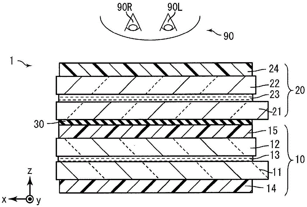
[0075] figure 1 It is a schematic cross-sectional view showing the configuration of the stereoscopic display device 1 according to the first embodiment of the present invention. The stereoscopic display device 1 includes a display panel 10 , a switch liquid crystal panel 20 , and an adhesive resin 30 . The display panel 10 and the switch liquid crystal panel 20 are arranged to overlap each other so that the switch liquid crystal panel 20 faces the viewer 90 side, and are bonded together with an adhesive resin 30 .

[0076] The display panel 10 includes a TFT (Thin Film Transistor: Thin Film Transistor) substrate 11 , a CF (Color Filter: Color Filter) substrate 12 , a liquid crystal layer 13 , and polarizing plates 14 and 15 . The display panel 10 controls the TFT substrate 11 and the CF substrate 12, manipulates the alignment of liquid crystal molecules in the liquid crystal layer 13, and displays images.

[0077] The switch liquid crystal pan...

no. 2 Embodiment approach

[0188] Figure 26 It is a cross-sectional view showing a schematic configuration of a stereoscopic display device 2 according to a second embodiment of the present invention. The stereoscopic display device 2 includes a switch liquid crystal panel 60 instead of the switch liquid crystal panel 20 .

[0189] The switch liquid crystal panel 60 includes a first substrate 61 instead of the first substrate 21 of the switch liquid crystal panel 20 , and a second substrate 62 instead of the second substrate 22 .

[0190] Formed on the first substrate 61 are supplied 12 kinds of signals V A ~V L electrodes 611A to 611L. The electrodes 611A to 611L are periodically formed in the x direction similarly to the electrodes 211B to 211K of the first substrate 21 . On the second substrate 62 , the common electrode 621COM is formed so as to cover substantially the entire surface of the active region of the second substrate 62 . Common electrode 621COM is supplied with signal V COM .

[0...


PUM


Abstract

The present invention obtains a three-dimensional display device configuration capable of reducing brightness variation when an observer moves by improving the angular dependence of brightness. A three-dimensional display device (1) is provided with a display panel (10), a switching liquid crystal panel (20), a first polarization plate (15), a second polarization plate (24), a position sensor for acquiring position information about an observer, and a control unit for moving a parallax barrier, in which transparent regions and opaque regions are formed periodically along a prescribed alignment direction, along the alignment direction in accordance with the position information and displaying the parallax barrier on the switching liquid crystal panel (20). The widths of the transparent regions are wider than the widths in the alignment direction of the openings of a plurality of pixels (110). The switching liquid crystal panel (20) includes a first substrate (21), a first orientation film (216), a second substrate (22), a second orientation film (226), and a liquid crystal layer (23). The rubbing direction of the first orientation film (216) is parallel to the transmission axis of the first polarization plate (15), and the rubbing direction of the second orientation film (226) is parallel to the transmission axis of the second polarization plate (24).

Description

technical field [0001] The invention relates to a naked-eye stereoscopic display device. Background technique [0002] A parallax barrier system and a lenticular lens system are known as stereoscopic display devices that can be viewed with the naked eye. These three-dimensional display devices use barriers or lenses to separate light, and map different images in the left and right eyes, giving the observer a three-dimensional sense. In recent years, the parallax barrier method and the lenticular lens method of two viewpoints of naked-eye stereoscopic display devices appearing in the market have become mainstream. [0003] These dual-view stereoscopic display devices can obtain good stereoscopic display in the set area, but when the observer moves his head, the image that should be mapped to the right eye and the image that should be mapped to the left eye will mix, resulting in double The mapped phenomenon is called crosstalk, or an image that should be mapped to the right...

Claims


Application Information

Patent Timeline
Patent Type & Authority Applications(China)
IPC IPC(8): G02F1/13G02B27/22G02F1/1333G02F1/1347G09F9/00H04N13/04G02B30/25G02B30/31
CPCH04N2213/001G02F1/1347H04N13/31H04N13/366G02F1/133784G02F1/134309G02F1/31G02B30/25G02F1/133531G02B30/31G02B30/27
Inventor 村尾岳洋菊地亮吉野拓人福岛浩
Owner SHARP KK
Why Eureka
Try Eureka