Lighting unit and liquid crystal display device including the lighting unit

a liquid crystal display device and lighting unit technology, applied in lighting and heating apparatus, identification means, instruments, etc., can solve the problems of difficult to completely eliminate the adverse effects of adjacent light-emitting elements, the quality of the image displayed might deteriorate, etc., to achieve the effect of improving display quality and reducing luminance variation

Inactive Publication Date: 2005-06-23
SHARP KK
View PDF13 Cites 19 Cited by
  • Summary
  • Abstract
  • Description
  • Claims
  • Application Information

AI Technical Summary

Benefits of technology

[0012] In order to overcome the problems described above, preferred embodiments of the present invention provide a lighting unit that causes a drastically reduced luminance variation and also provide a liquid crystal display device that realizes significantly improved display quality by using the lighting unit.
[0025] In the lighting unit according to preferred embodiments of the present invention, the light-emitting elements are respectively provided for the light-emitting regions, and the controller supplies drive signals of substantially different types to at least two of these light-emitting elements, thereby controlling the emission intensities of the light-emitting elements to mutually different levels. As already described for the background of the invention, even if the light-emitting elements have the same emission intensity, the light-emitting regions may have mutually different luminance values. This is because a light-emitting region illuminated by one of the light-emitting elements may be affected by the light emitted from an adjacent one of the light-emitting elements. Even so, if the emission states of the light-emitting regions are controllable independently by varying the emission intensities of the light-emitting elements intentionally, the luminances of the light-emitting regions can be substantially equalized with each other. As a result, the lighting unit as a whole can emit light having a uniform luminance without causing the unwanted variation in luminance. Accordingly, a liquid crystal display device including a lighting unit like this can display a motion picture at a desired high rate.

Problems solved by technology

However, when a motion picture is displayed at a high rate on a liquid crystal display device, the resultant quality of the image displayed might deteriorate.
But it is very difficult to completely eliminate the adverse effects of the adjacent light-emitting element on the light-emitting region.
A problem like this may also arise in a lighting unit including no partitions between the light-emitting elements.

Method used


Image

  • Lighting unit and liquid crystal display device including the lighting unit
  • Lighting unit and liquid crystal display device including the lighting unit
  • Lighting unit and liquid crystal display device including the lighting unit

Examples


embodiment 1

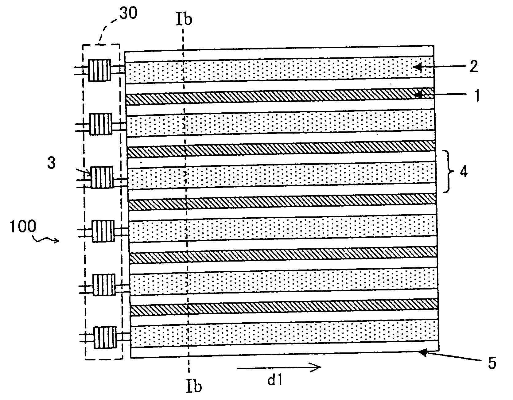
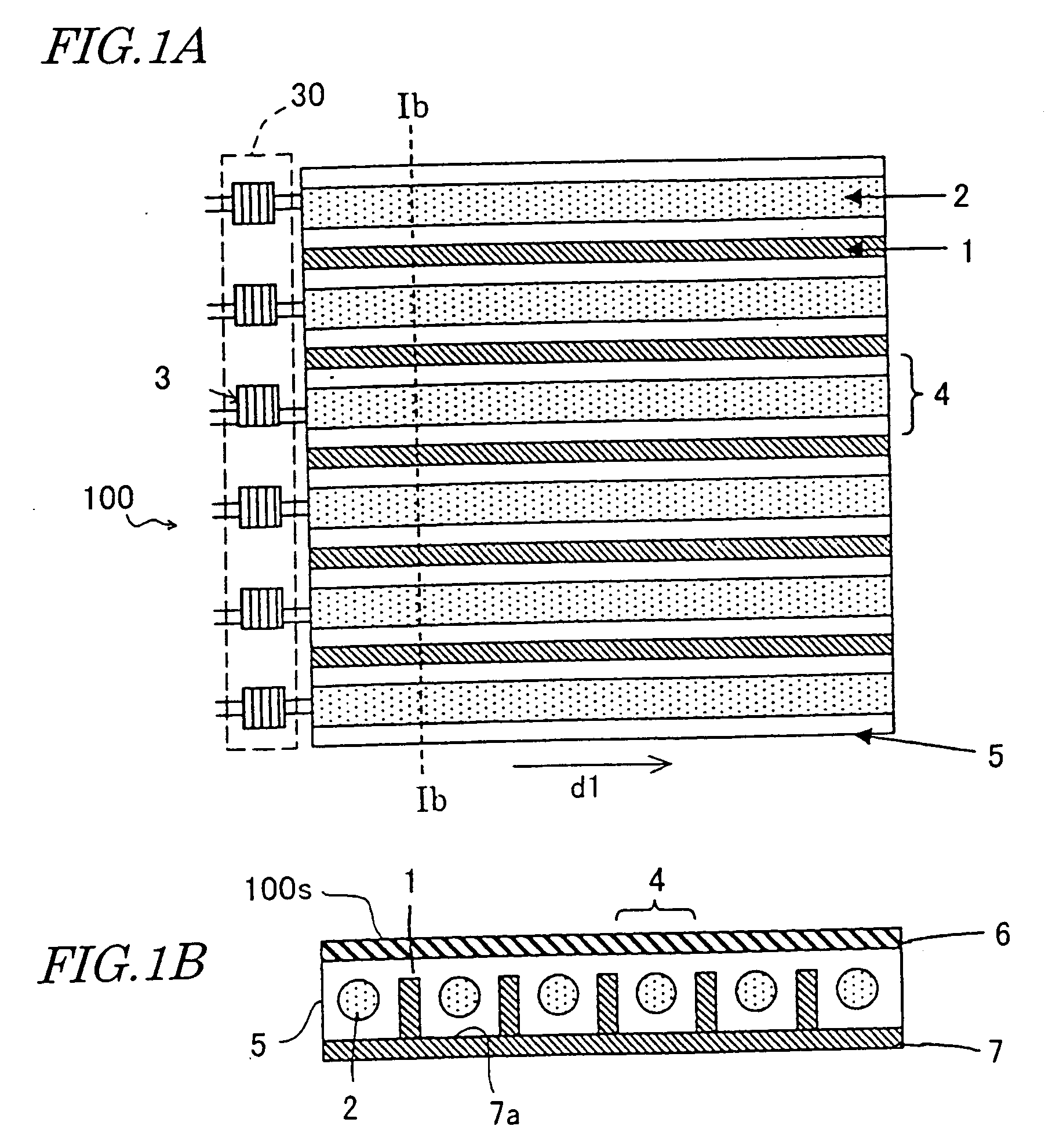
[0056] Hereinafter, a lighting unit according to a first specific preferred embodiment of the present invention will be described with reference to FIGS. 1 through 19B. In FIGS. 1 through 19B, any member illustrated in multiple drawings but having substantially the same function will be identified by the same reference numeral.

[0057]FIGS. 1A and 1B are respectively a plan view of a lighting unit 100 according to the first preferred embodiment and a cross-sectional view thereof taken along the line Ib-Ib shown in FIG. 1A. The lighting unit 100 may have approximate dimensions of 32 cm (vertically)×40.5 cm (horizontally)×2.5 cm (thickness). As shown in FIGS. 1A and 1B, the lighting unit 100 includes a reflector 7 with a reflective plane 7a, a diffuser 6 that faces the reflective plane 7a of the reflector 7, and a plurality of light-emitting elements 2 interposed between the reflector 7 and the diffuser 6. These members 2, 6 and 7 are stored inside a casing 5.

[0058] A number of partit...

embodiment 2

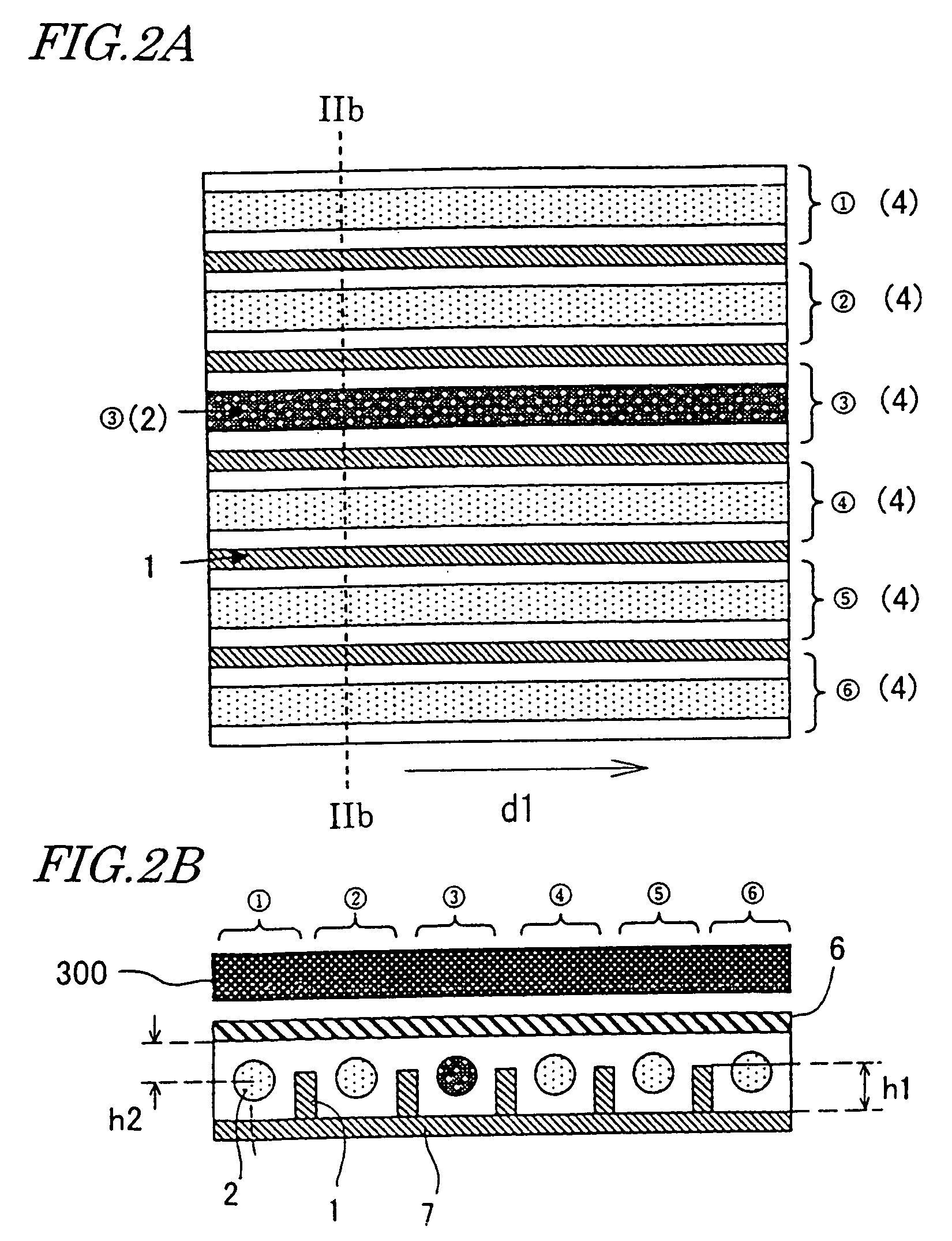
[0097] Hereinafter, a lighting unit according to a second specific preferred embodiment of the present invention will be described with reference to FIGS. 20A through 23. In FIGS. 20A through 23, any member illustrated in multiple drawings but having substantially the same function will be identified by the same reference numeral.

[0098] As shown in FIG. 20A, the lighting unit 200 of the second preferred embodiment includes not only all the components of the lighting unit 100 of the first preferred embodiment but also instruments 10 for measuring the luminances of the respective light-emitting regions and a circuit (not shown) for feeding back the luminance information to the lighting controller 30.

[0099] Photodiodes may be used as the instruments 10. By using the photodiodes, the variation in luminance of each light-emitting region with time and the difference in luminance between the light-emitting regions can be detected. As long as the instruments 10 can detect the luminances o...


PUM

PropertyMeasurementUnit
thicknessaaaaaaaaaa
distance h2aaaaaaaaaa
height h1aaaaaaaaaa

Abstract

A lighting unit includes a reflector, a plurality of light-emitting elements and a controller. The light-emitting elements are respectively provided on the reflector for a plurality of light-emitting regions. The controller supplies a periodic drive signal to each of the light-emitting elements, thereby defining a state of the light-emitting element. The lighting unit illuminates a display panel including a light modulating layer with light that has been emitted from the light-emitting elements. The controller supplies drive signals of substantially different types to at least two of the light-emitting elements.

Description

BACKGROUND OF THE INVENTION [0001] 1. Field of the Invention [0002] The present invention relates to a lighting unit for use as a backlight in a liquid crystal display device, for example, and also relates to a liquid crystal display device that uses the lighting unit. [0003] 2. Description of the Related Art [0004] A liquid crystal display device has a number of advantageous features including light weight, reduced thickness and low power consumption. Thus, a liquid crystal display device is now used extensively in office automation appliances, car mount TV sets, camcorder monitors and so on. However, when a motion picture is displayed at a high rate on a liquid crystal display device, the resultant quality of the image displayed might deteriorate. For example, the image once displayed thereon might lag or smear due to the low response of its liquid crystal molecules to an applied voltage. [0005] According to a known technique, a quality motion picture may be displayed on a transmi...

Claims


Application Information

Patent Timeline
Patent Type & Authority Applications(United States)
IPC IPC(8): G02F1/133G02F1/1335G02F1/13357G09F9/00G09F9/35G09G3/34G09G3/36
CPCG02F1/133605G02F1/133608G09G3/342G09G3/36G09G3/3611G09G2310/0232G09G2360/145G09G2310/08G09G2320/02G09G2320/0233G09G2320/0261G09G2320/0626G09G2320/064G09G2310/024G02F1/1335
Inventor KAWABATA, MASAESHIOMI, MAKOTO
Owner SHARP KK
Why Eureka
Try Eureka