Stereoscopic display device

a display device and naked eye technology, applied in the field of naked eye stereoscopic display devices, can solve the problems of changing and achieve the effect of reducing the variation of luminance and increasing crosstalk

Active Publication Date: 2016-07-07
SHARP KK
View PDF5 Cites 18 Cited by
  • Summary
  • Abstract
  • Description
  • Claims
  • Application Information

AI Technical Summary

Benefits of technology

[0009]According to the present invention, a stereoscopic display device can be obtained wherein luminance vari...

Problems solved by technology

Actually, however, there is a delay time due to the response speed of liquid ...

Method used


Image

  • Stereoscopic display device
  • Stereoscopic display device
  • Stereoscopic display device

Examples


embodiments

[0110]The following describes embodiments of the present invention in detail, while referring to the drawings. In the drawings, identical or equivalent parts are denoted by the same reference numerals, and the descriptions of the same are not repeated. To make the explanation easy to understand, in the drawings referred to hereinafter, the configurations are simplified or schematically illustrated, or a part of constituent members are omitted. Further, the dimension ratios of the constituent members illustrated in the drawings do not necessarily reflect the real dimension ratios.

first embodiment

The First Embodiment

Overall Configuration

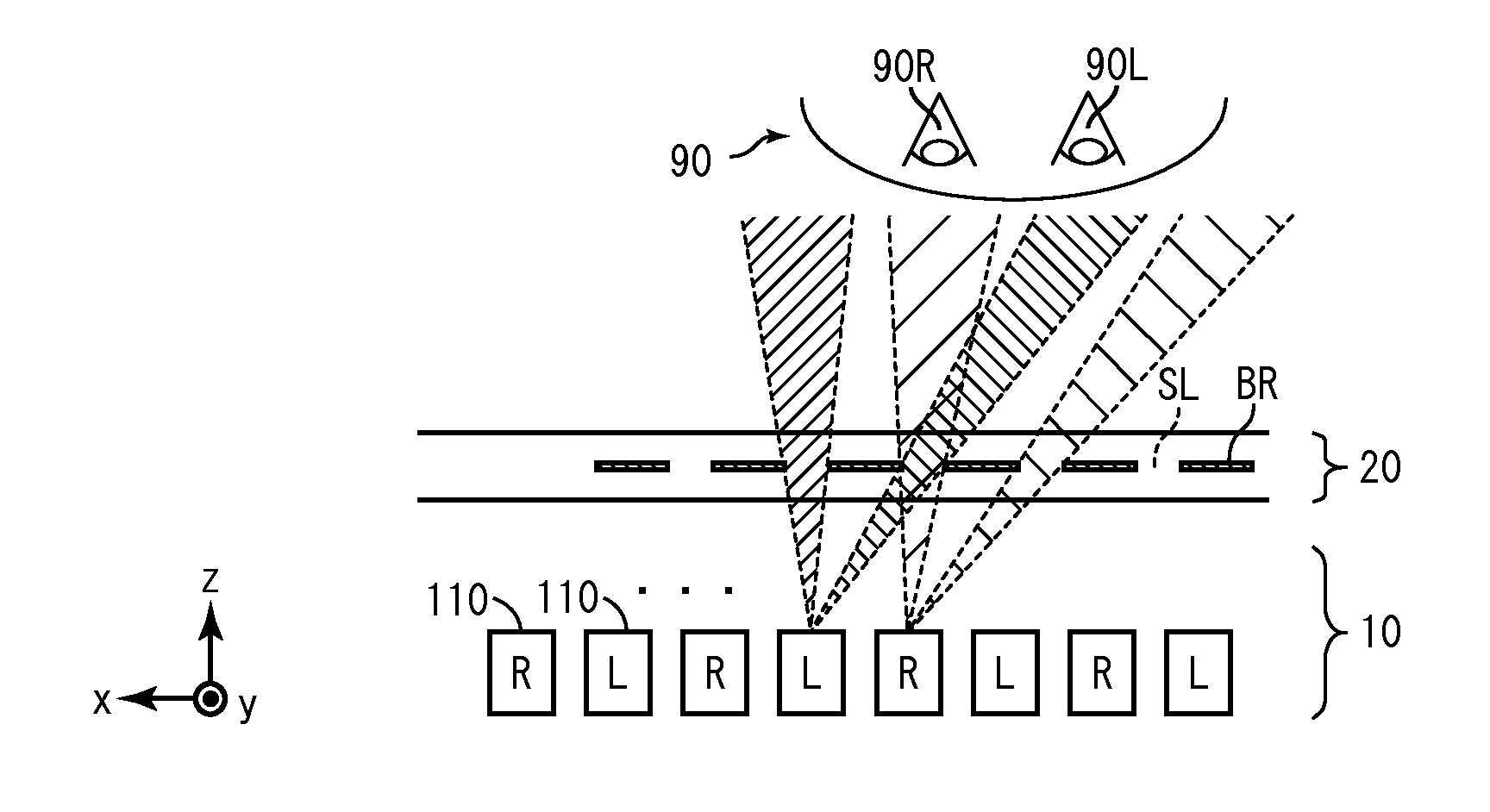
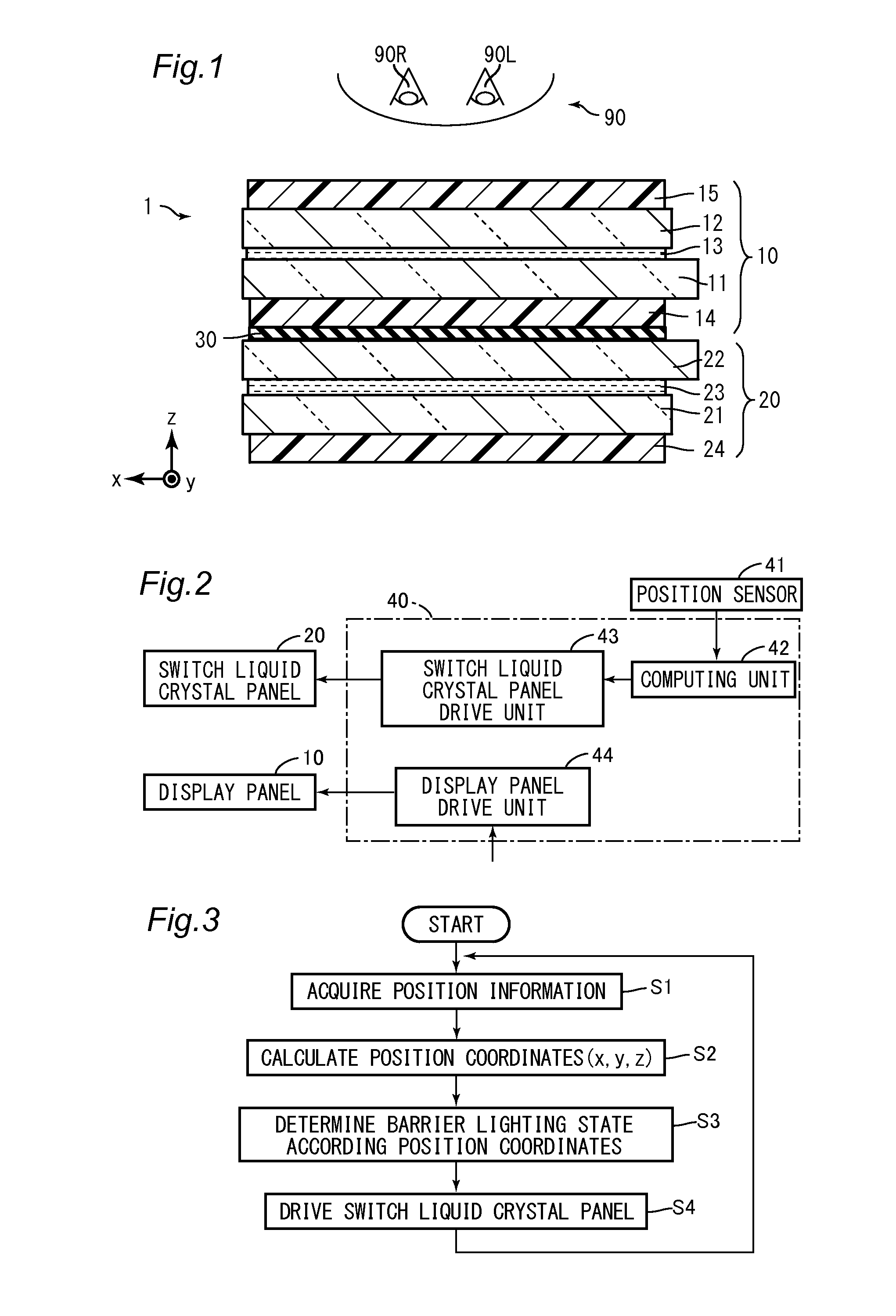
[0111]FIG. 1 is a schematic cross-sectional view illustrating a configuration of a stereoscopic display device 1 according to the First Embodiment of the present invention. The stereoscopic display device 1 includes a display panel 10, a switch liquid crystal panel 20, and an adhesive resin 30. The display panel 10 and the switch liquid crystal panel 20 are arranged so as to be stacked in such a manner that the display panel 10 is positioned on the viewer 90 side, and are stuck with each other with the adhesive resin 30.

[0112]The display panel 10 includes a TFT (thin film transistor) substrate 11, a CF (color filter) substrate 12, a liquid crystal layer 13, and polarizing plates 14 and 15. The display panel 10 controls TFT substrate 11 and the CF substrate 12 so as to operate the alignment of liquid crystal molecules in the liquid crystal layer 13, thereby to display images.

[0113]The switch liquid crystal panel 20 includes a first substrate 2...

second embodiment

The Second Embodiment

[0215]FIG. 26 is a cross-sectional view illustrating a schematic configuration of a stereoscopic display device 2 according to the Second Embodiment of the present invention. The stereoscopic display device 2 includes a display panel 50 in the place of the display panel 10, and includes a switch liquid crystal panel 60 in the place of the switch liquid crystal panel 20.

[0216]The display panel 50 includes pixels 510 in the place of the pixels 110. The configuration of the pixel 510 is to be described below.

[0217]The switch liquid crystal panel 60 includes a second substrate 62 in the place of the second substrate 22. FIG. 27 is a plan view illustrating a configuration of a second substrate 62. On the second substrate 62, a second electrode group 221 is formed in the place of the common electrode 221COM. The second electrode group 221 includes a plurality of electrodes that are arranged in the x direction at an electrode pitch BP. The plurality of electrodes exten...


PUM


Abstract

Obtained is a configuration of a stereoscopic display device wherein luminance variation and increase of crosstalk can be reduced over a period before and after the switching of the parallax barrier. The stereoscopic display device includes: a display panel for displaying an image with a plurality of pixels; a switch liquid crystal panel that is arranged so as to be stacked on the display panel; a position sensor for acquiring position information of a viewer; and a control unit for moving a parallax barrier in which transmitting regions and non-transmitting regions are formed in periodic fashion in a predetermined alignment direction, in such a manner that the parallax barrier is moved in the predetermined alignment direction in accordance with the position information, with use of a predetermined barrier switching pitch as a minimum unit, and causing the switch liquid crystal panel to display the parallax barrier. The plurality of pixels have openings each of which has a width A in the alignment direction, the width A satisfying the expressions of A≦Wsl−2Pe, and A≦Wbr−2Pe where Wsl is a width of the transmitting region, Wbr is a width of the non-transmitting region BR, and Pe is the barrier switching pitch.

Description

TECHNICAL FIELD[0001]The present invention relates to a naked-eye stereoscopic display device.BACKGROUND ART[0002]As a stereoscopic display device that can be viewed with naked eyes, those of a parallax barrier type and a lenticular lens type are known. The stereoscopic display devices of these types separate light using barriers or lenses, and cause different images to be visible to the right and left eyes, respectively, so as to provide a stereoscopic vision to the viewer. In recent years, main types of naked-eye stereoscopic display devices that are in the market are those of the two-viewpoint parallax barrier type and those of the lenticular lens type.[0003]In the case of such a two-viewpoint stereoscopic display device, excellent stereoscopic display can be achieved from a predetermined region, but there also exists the following region: when a viewer moves the head to the region, a so-called crosstalk occurs, which is such a phenomenon that an image to be visible to the right ...

Claims


Application Information

Patent Timeline
IPC IPC(8): G02B27/22G02F1/29G02B30/31
CPCG02F1/292G02B27/2214G02F1/1347G03B35/24H04N13/376H04N13/31G02B30/31G02F1/1323G02B30/27
Inventor MURAO, TAKEHIROYOSHINO, TAKUTOFUKUSHIMA, HIROSHI
Owner SHARP KK
Why Eureka
Try Eureka