Discharge lamp lighting apparatus for lighting multiple discharge lamps

Inactive Publication Date: 2006-02-09
MINEBEA CO LTD
View PDF14 Cites 21 Cited by
  • Summary
  • Abstract
  • Description
  • Claims
  • Application Information

AI Technical Summary

Benefits of technology

[0029] According to a second aspect of the present invention a discharge lamp lighting apparatus, which lights a plurality of discharge lamps, includes: a DC power supply; a control circuit to output signals; a step-up transformer defining a primary side and a secondary side; switching elements connected to the DC power supply and adapted to drive the primary side of the step-up transformer based on the signals from the control circuit so as to light the plurality of discharge lamps which include one reference discharge lamp and at least one controllable discharge lamp, and which are connected to the secondary side of the step-up transformer. The discharge lamp lighting apparatus further includes: an inductance element provided between one terminal of the secondary side of the step-up transformer and one terminal of the reference discharge lamp; a first lamp current detecting unit connected to the other terminal of the reference discharge lamp; a first series resonant circuit constituted by a leakage inductance of the step-up transformer, an inductance of the inductance element, and a capacitance of a capacitance element together with a stray capacitance provided between the inductance element and the reference discharge lamp; at least one variable inductance element provided between the one terminal of the secondary side of the step-up transformer and one terminal of the controllable discharge lamp; at least one second lamp current detecting unit connected to the other terminal of the controllable discharge lamp; at least one lamp current controlling circuit connected to the variable inductance element; and at least one second series resonant circuit constituted by the leakage inductance of the step-up transformer, an inductance of the variable inductance element, and a capacitance of a capacitance element together with a stray capacitance provided between the variable inductance element and the controllable discharge lamp. In the discharge lamp lighting apparatus described above, an output signal from the first lamp current detecting unit connected to the reference discharge lamp and also an output signed from the second lamp current detecting unit connected to the controllable discharge lamp are connected to the lamp current controlling circuit for the controllable discharge lamp, and an output signal from the lamp current controlling circuit for the controllable discharge lamp is connected to the variable inductance element for the controllable discharge lamp so as to vary the inductance of the variable inductance element for the controllable discharge lamp t

Problems solved by technology

In such a backlight device, if brightness varies from one discharge lamp to another, the display screen of the LCD apparatus incurs non-uniformity thus significantly degrading the display quality.
This approach, however, requires an increased number of components thus pushing up cost, which eventually results in an increased cost of the discharge lamp lighting apparatus.
Consequently, the number of components is increased pushing up the cost on the discharge lamp lighting apparatus.
Also, since a high voltage is applied to the capacitors 110a an 110b an described above, t

Method used


Image

  • Discharge lamp lighting apparatus for lighting multiple discharge lamps
  • Discharge lamp lighting apparatus for lighting multiple discharge lamps
  • Discharge lamp lighting apparatus for lighting multiple discharge lamps

Examples


first embodiment

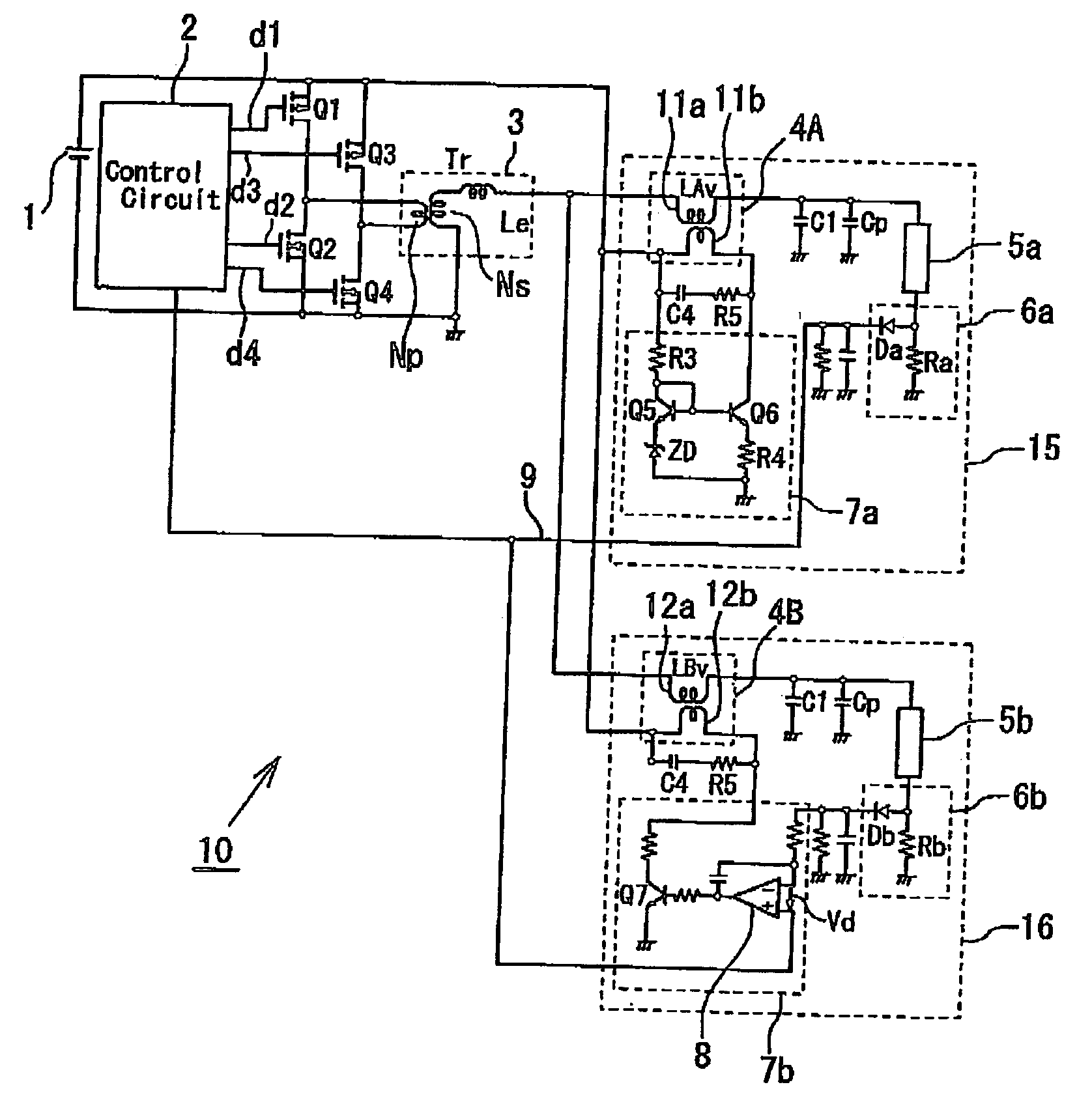
[0037] Referring to FIG. 1, a discharge lamp lighting apparatus 10 according to the present invention is adapted to light a plurality (two in the present embodiment) of discharge lamps 5a and 5b, for example cold-cathode tubes. In the discharge lamp light apparatus 10, a series circuit including transistors Q1 and Q2 as switching elements and a series circuit including transistors Q3 and Q4 as switching elements are connected in parallel across both electrodes of a DC power supply 1, and the connection portion of the transistors Q1 and Q2 is connected to one terminal of a primary winding NP of a step-up transfer 3 while the connection portion of the transistors Q3 and Q4 is connected to the other terminal of the primary winding Np of the step-up transformer 3, whereby what is called “a full-bridge connection” is formed.

[0038] A control circuit 2 controls the discharge lamp lighting apparatus 10, includes an oscillation circuit to set a driving frequency for driving the primary side ...

second embodiment

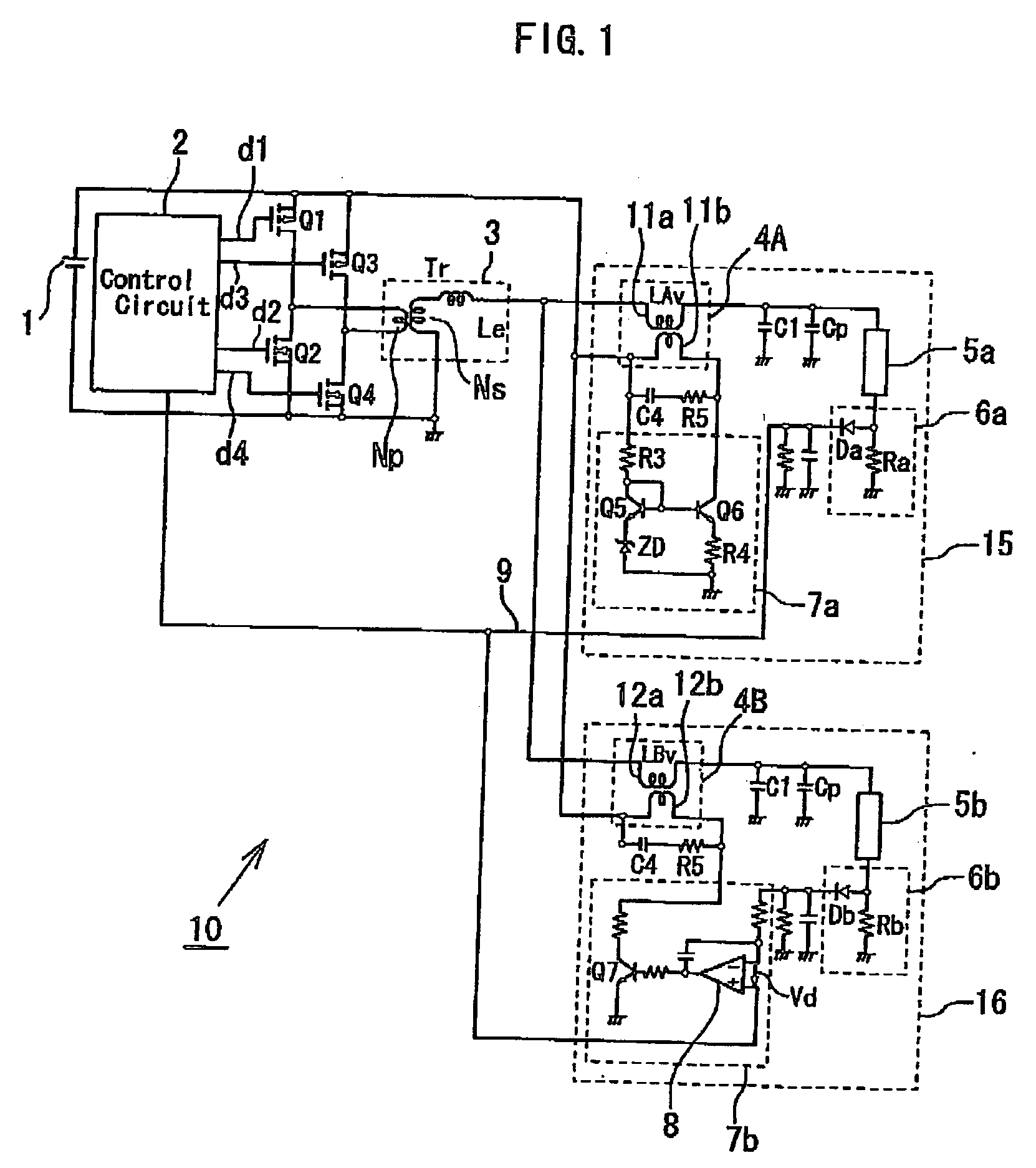
[0058] Referring to FIG. 2, a discharge lamp lighting apparatus 20 according to the present invention is for lighting three discharge lamps 5a, 5b and 5c. In the discharge lamp lighting apparatus 20, the discharge lamp 5c as another controllable lamp is connected to a secondary side lighting circuit 17 which is identical with the secondary side lighting circuit 16 including the discharge lamp 5b shown in FIG. 1, and which is connected, in parallel with secondary side lighting circuits 15 and 16, to the secondary side of a step-up transformer 3. The discharge lamp lighting apparatus 20 operates in the same way as the discharge lamp lighting apparatus 10 of FIG. 1, and the lamp currents of the discharge lamps 5b and 5c as controllable lamps are controlled to match up to the lamp current of the discharge lamp 5a as a reference lamp.

third embodiment

[0059] Referring now to FIG. 3, a discharge lamp lighting apparatus 30 according to the present invention employs an inductor (ordinary inductor) 13 as an inductance element in a secondary side lighting circuit 15 including a discharge lamp 5a as a reference lamp, in place of the transformer 4A and the lamp current controlling circuit 7a connected to the control winding 11b (refer to FIGS. 1 and 2). This circuitry reduces the number of components thereby contributing to reduction in cost. In this connection, an inductance Lf of the inductor 13 is set at Lmin+ΔL / 2 in order to control an inductance LBv of a winding 12a of a transformer 4B near the median value (1 min+ΔL / 2) of the variable range, and since the inductor 13 generally has a magnetic characteristic different from that of a variable inductance element, a careful design work is required. The selection between the discharge lamp lighting apparatus 10 of FIG. 1 and the discharge lamp lighting apparatus 30 of FIG. 3 is to be ma...


PUM


Abstract

A discharge lamp lighting apparatus is provided for lighting a plurality of discharge lamps including one reference lamp and at least one controllable lamp. First variable inductance element and lamp current detecting unit are connected to the reference lamp, second variable inductance and lamp current unit are connected to the controllable lamp, and a lamp current controlling circuit is connected to each of the first and second variable inductance elements. An output signal from the second lamp current detecting unit and also an output signal as a reference signal from the first lamp current detecting unit are connected to the lamp current controlling circuit for the controllable lamp, whereby the lamp current of the controllable lamp is controlled. The reference output signal is also connected to a control circuit, and the lamp currents of the reference and controllable lamps are controlled further by the on/off operation of the switching elements.

Description

BACKGROUND OF THE INVENTION [0001] 1. Field of the Invention [0002] The present invention relates to a discharge lamp lighting apparatus, and more particularly to a discharge lamp lighting apparatus to light a plug of discharge lamps. [0003] 2. Description of the Related Art [0004] A liquid crystal display (LCD) apparatus as a flat panel display apparatus is used in various applications. Since a liquid crystal in the LCD apparatus does not emit light by itself, a lighting device is required separately in order to achieve a good display. A backlight device to light a liquid crystal panel from behind is one type of lighting device. The backlight device uses primarily a cold cathode lamp as a discharge lamp and incorporates a discharge lamp lighting apparatus including an inverter to drive the cold cathode lamp. [0005] Recently, the LCD apparatus is becoming larger and larger for use in, for example, a large-screen TV, and therefore a plurality of discharge lamps are used in a backligh...

Claims


Application Information

Patent Timeline
IPC IPC(8): H05B39/04H05B41/36H05B37/02H02M7/48H05B41/24
CPCH05B41/2827H05B41/26
Inventor SHINMEN, HIROSHIMATSUSHIMA, MITSUONISHIBORI, KOHEI
Owner MINEBEA CO LTD
Why Eureka
Try Eureka