Washing machine and deceleration clutch for same

A deceleration clutch and washing machine technology, applied in the field of washing machines, can solve problems such as poor overrunning clutch, failure of one-way bearings, large vibration of washing machines, etc., and achieve the effects of simple and reliable structure, improved bearing capacity, and improved washing ratio

Active Publication Date: 2016-07-06
QINGDAO HAIER WASHING MASCH CO LTD
View PDF6 Cites 3 Cited by
  • Summary
  • Abstract
  • Description
  • Claims
  • Application Information

AI Technical Summary

Problems solved by technology

[0006] However, in the washing machine with the above-mentioned deceleration clutch, the inner tub and the pulsator frequently run in opposite directions, and the moment of inertia generated by the inner tub directly acts on the overrunning clutch. quality problem
During the rotation of the inner tub, the one-way bearing will often have a reverse force, and the one-way bearing is prone to failure. At the same time, the clutch spring will be tightened during washing, resulting in damage to the clutch spring; The driving wheel is separated and connected to the reducer. The inner drum swings in the dehydration state, which directly acts on the dehydration shaft. The dehydration shaft is eccentric, causing the washing machine to vibrate and produce noise.

Method used


Image

  • Washing machine and deceleration clutch for same
  • Washing machine and deceleration clutch for same
  • Washing machine and deceleration clutch for same

Examples


Embodiment Construction

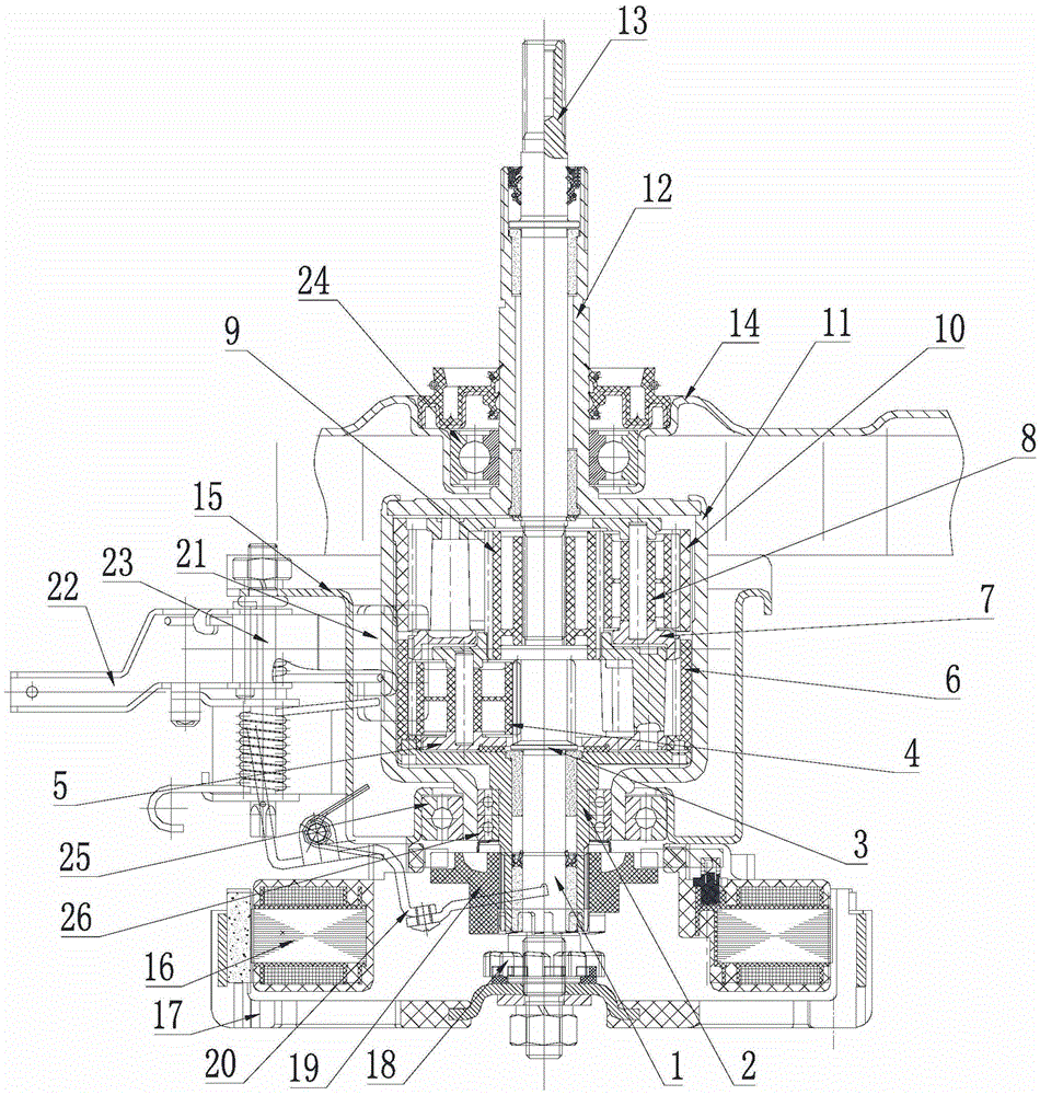
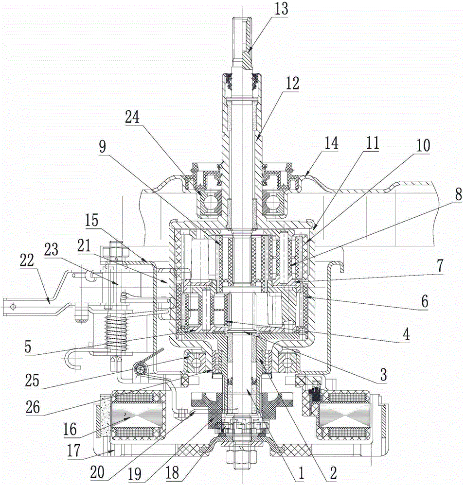
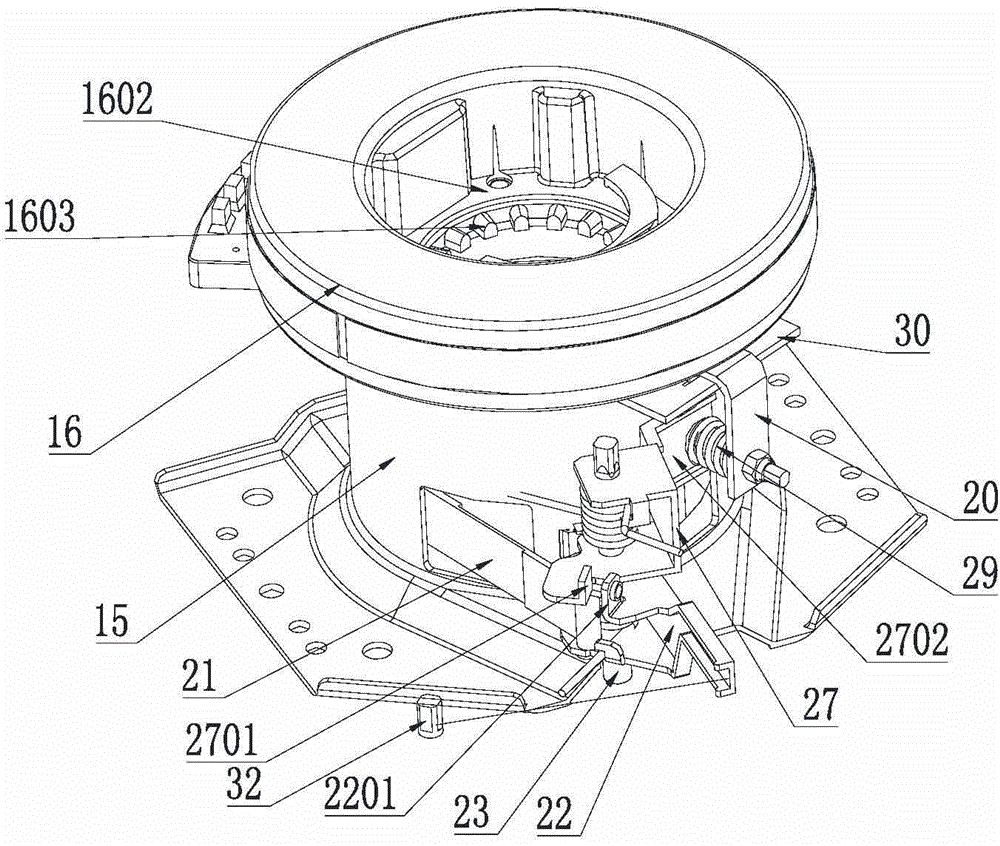
[0038] Such as figure 1 , figure 2 , image 3 , Figure 4 , Figure 5 , Figure 6 , Figure 7 , Figure 8 As shown, a deceleration clutch for a washing machine according to the present invention at least includes a housing, a brake wheel 11 located in the housing, and a wheel train located in the brake wheel 11. The lower part of the housing is fixedly connected to a direct drive motor, and the direct drive The cavity of the motor stator 16 is provided with a clutch sleeve 19 that can slide up and down, and the clutch sleeve 19 slides up and down to connect with the torque transmission sleeve 18 and the fixed sleeve respectively to realize dehydration and washing. The clutch sleeve 19 is driven by a shift fork 20, There is a gap between the inner side wall of the stator 16 and the outer side wall of the clutch shaft sleeve 19, and the stator 16 is located at the top of the gap and is provided with a gap 1601, and the shift fork 20 extends into the gap 1601, at least par...


PUM


Abstract

The invention relates to a deceleration clutch for a washing machine. The deceleration clutch comprises a shell, a brake wheel in the shell and a wheel system in the brake wheel, and further comprises a clutch shaft sleeve capable of sliding up and down and a shifting fork driving the clutch shaft sleeve. A brake belt is arranged between the shell and the brake wheel. The brake belt surrounds the brake wheel, one end of the brake belt is fixedly installed on the shell, and the other end of the brake belt stretches out of the shell to be connected with a brake arm. The brake arm is arranged on a center shaft. The center shaft is fixedly installed on the shell. A connecting arm is arranged on the center shaft and located on the lower portion of the brake arm. The brake arm drives the connecting arm to move. The connecting arm drives the brake belt and the shifting fork to move, and the clutch shaft sleeve is driven to slide up and down to be connected with a torque shaft sleeve and a fixed shaft sleeve respectively to achieve dehydration and washing.

Description

technical field [0001] The invention relates to the field of washing machines, in particular to a deceleration clutch for washing machines and a washing machine. Background technique [0002] At present, the function of the deceleration clutch of the pulsator type washing machine is generally to drive the pulsator to reciprocate after decelerating the bidirectional rotation of the motor. The conventional deceleration clutch is mainly composed of an input shaft, an output shaft, an output shaft sleeve, an input shaft sleeve, a brake wheel, a reduction mechanism installed inside the brake wheel, and a clutch component installed on the input shaft sleeve. In washing conditions, the output shaft is required to rotate repeatedly at low speed in both directions. The output shaft sleeve and the brake wheel are integrated. The deceleration mechanism generally only plays a simple deceleration role. When the brake wheel is braked, the output shaft sleeve is also restrained. The two-w...

Claims


Application Information

Patent Timeline
Patent Type & Authority Applications(China)
IPC IPC(8): D06F37/30D06F17/08F16D67/02
Inventor 舒海杨林张刚金
Owner QINGDAO HAIER WASHING MASCH CO LTD
Why Eureka
Try Eureka