
Track wear automatic detection vehicle
An automatic detection and track technology, applied in measuring devices, instruments, etc., can solve the problems of high work intensity, affecting the operation safety of the conveying system, sinking of the spreader trolley, etc. The effect of work intensity
- Summary
- Abstract
- Description
- Claims
- Application Information
AI Technical Summary
Problems solved by technology
Method used
Image

Examples
Embodiment Construction
[0016] The present invention will be further described below in conjunction with specific examples.
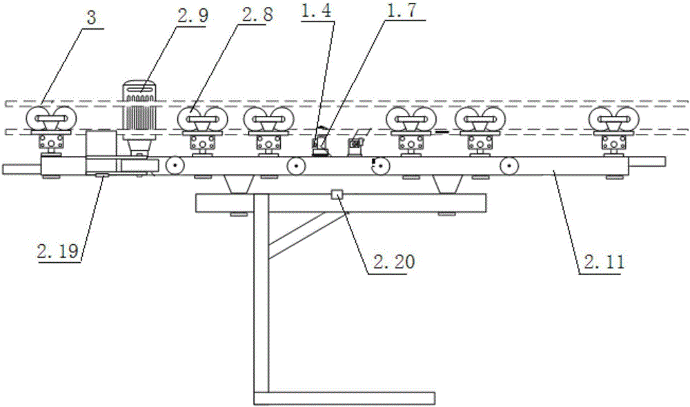
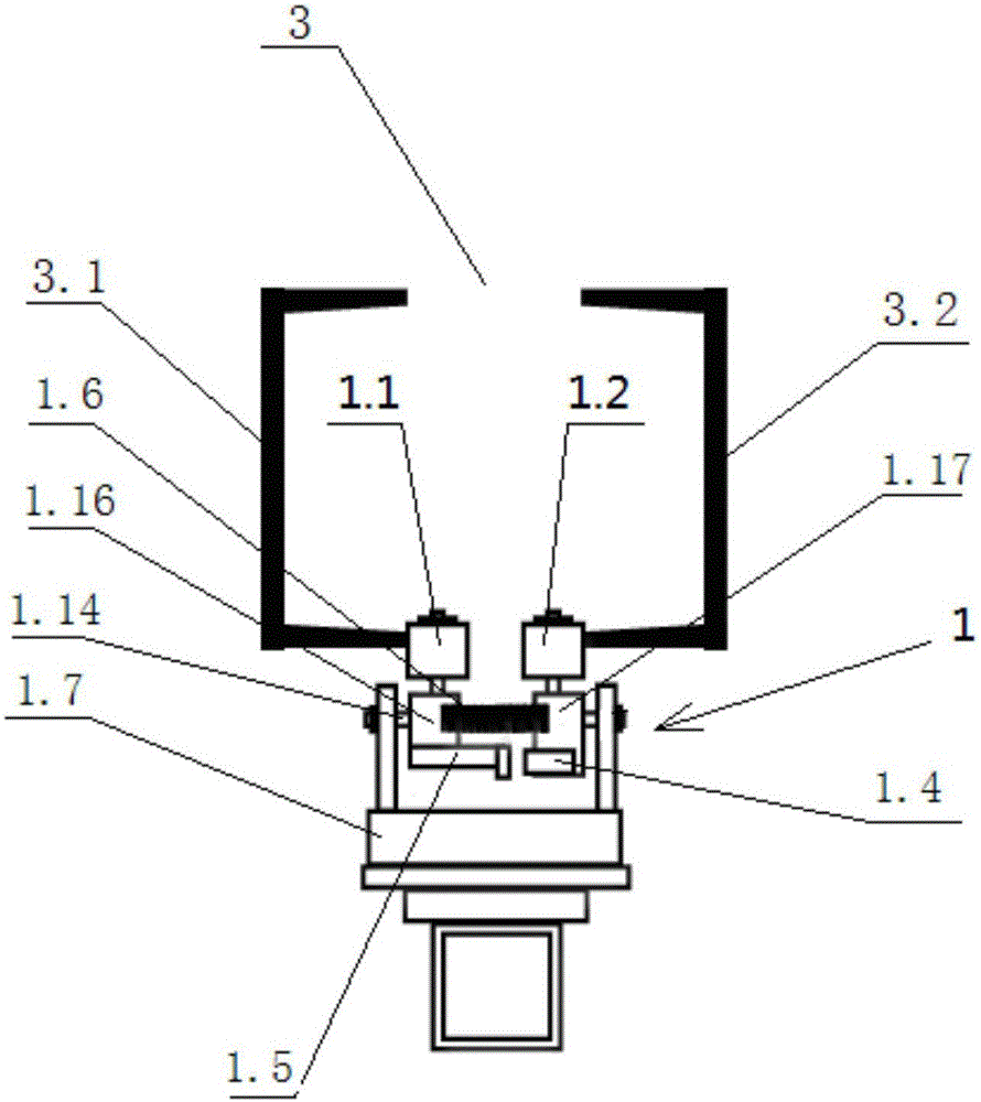
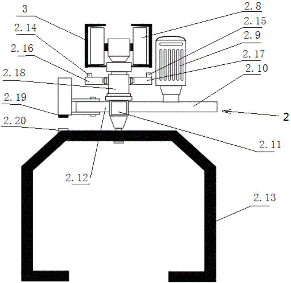
[0017] The track wear automatic detection vehicle is equipped with a track transverse gap detection device 1 and a track vertical wear detection device 2 on the track 3, and the track 3 includes a left track monomer 3.1 and a right track monomer 3.2;
[0018] The track transverse gap detection device 1 includes a first detection wheel 1.1, a second detection wheel 1.2, a displacement sensor 1.4, a detection label 1.5, a compression spring 1.6 and a mounting bracket 1.7, and there are two left and right mounting plates on the mounting bracket 1.7, Mounting shaft 1.14 is fixed on the left mounting plate and the right mounting plate of mounting bracket 1.7, and the first mounting base 1.16 is slidably installed on the mounting shaft 1.14 of the left mounting plate close to mounting bracket 1.7, and is installed near the right mounting bracket 1.7 A second mount 1.17 is slidably i...
PUM
 Abstract
Description
Claims
Application Information