Automatic focusing device

An automatic focusing and focusing position technology, applied in focusing devices, installations, TVs, etc., can solve problems such as inability to focus accurately, unable to obtain focusing effects, focusing errors, etc., to solve problems such as inability to focus or long focusing time, improve focusing speed and Accuracy, Effects of Auxiliary Accuracy

Active Publication Date: 2016-07-20
BEIJING SPREADTRUM HI TECH COMM TECH CO LTD
View PDF4 Cites 5 Cited by
  • Summary
  • Abstract
  • Description
  • Claims
  • Application Information

AI Technical Summary

Problems solved by technology

[0015] It is impossible to focus well on subjects with thin lines and only weak textures, which may easily cause focus errors and take too long; in low-contrast and low-light conditions, the focus performance cannot be achieved well; Objects, polarized subjects, black subjects, or subjects with a mirror surface cannot be accurately focused
[0016] The focusing system and focusing method of the prior art cannot obtain a better focusing effect, thus affecting the imaging performance of the camera equipment

Method used


Image

  • Automatic focusing device
  • Automatic focusing device
  • Automatic focusing device

Examples


Embodiment 1

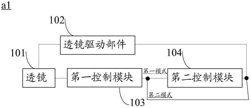
[0074] like image 3 The shown autofocus device a1 is suitable for an imaging device (similar in structure to the imaging device 1 ), and includes: a lens 101 , a lens driving component 102 , a first control module 103 and a second control module 104 .

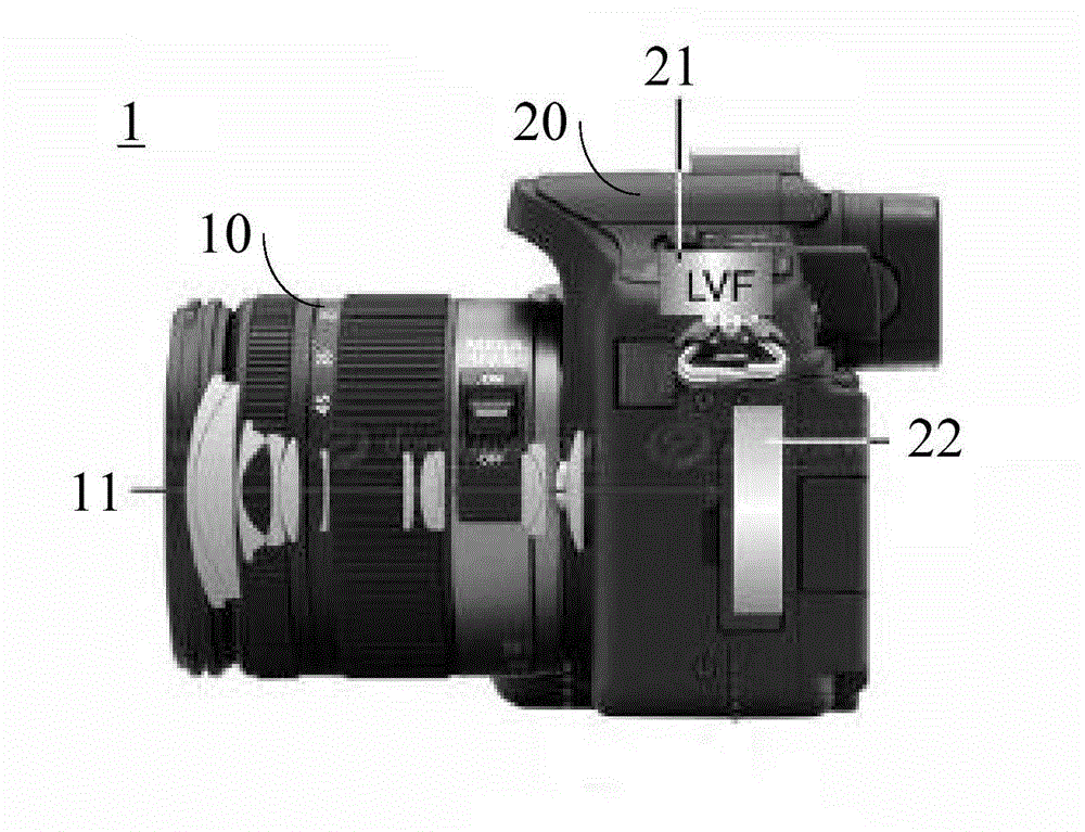
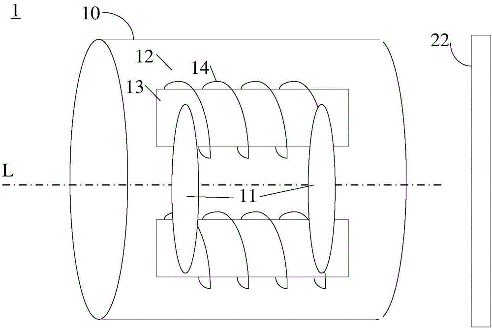
[0075] The lens 101 is provided in the lens system 10 and generally refers to a plurality of lenses on the same optical axis L of the imaging device 1 . The lens 101 includes a lens for automatic focus control, also called a focus lens. The focusing lens can move back and forth along the optical axis of the lens, and is driven by the response of the lens driving part 102 to the signal related to the focusing result (that is, the focusing signal), thereby moving the focusing lens and changing the lens position, and the lens position can be changed by The lens position detection part inside or outside the auto-focus device detects, which is beneficial to the re-driving of the subsequent focus lens. The original image can be gen...

Embodiment 2

[0148] This embodiment is different from the first embodiment, and it provides a method for denoising the pixels of the original image in parallel, where the pixels of the original image are collected in the form of focus detection windows.

[0149] Such as Figure 9 The shown autofocus device a2 includes: a lens 101, a lens driving component 102, a first control module 103' and a second control module 104. Wherein, the first control module 103' is adapted to obtain the first frequency response result of the pixel on the position of the image of interest in the original image in the first mode, and output the noise-reduced image based on the frequency response result of the passband part; and the first control The module 103' is further adapted to acquire the second frequency response result of the pixel at the position of interest in the original image in the second mode.

[0150] The focus detection window is adapted to capture an image position of interest in a raw image. ...

Embodiment 3

[0156] Such as Figure 11 In the shown autofocus device a4, different from the first embodiment, the first control module 103"' further includes: a statistics unit; The response value outputs the second frequency response result.

[0157] In the second mode, the output of the statistical unit is the one-to-one correspondence between the frequency response value of the pixel of interest on the original image and its corresponding frequency response result, and the corresponding relationship can be multiple under different function mappings, such as The summation or averaging involved in the first embodiment.

[0158] For one focusing process, the statistical unit may output the second frequency response result in the form of the focusing statistical curve described in the first embodiment.


PUM


Abstract

The invention discloses an automatic focusing device. The device comprises a lens, a lens drive component, a first control module and a second control module. The first control module is applicable for obtaining a first frequency response result of pixels of an original image in a first mode and outputting a noise reduction image based on the first frequency response result of a passband part. The second control module is applicable for extracting a space domain edge operator at an interested image position of the noise reduction image, correspondingly multiplying the space domain edge operator and the pixel values at the interested image position according to edge directions and summing, thus obtaining a space domain result. The first control module is also applicable for obtaining a second frequency response result of interested pixels of the original image in a second mode. The lens drive component is applicable for taking the lens position when an expected space domain result / the second frequency response result is realized, as a focusing position, thus driving the lens. According to the device, under the conditions of low contrast textures and weak light, the focusing accuracy and the focusing speed of a photographed object are improved.

Description

technical field [0001] The invention relates to the field of imaging, in particular to an automatic focusing device. Background technique [0002] Camera devices, such as cameras and mobile phones with integrated cameras, are usually capable of autofocus. [0003] Autofocus (AutoFocus) utilizes the principle of light reflection of the subject. The light reflected by the subject is accepted by the image sensor (such as CCD / CMOS sensor) of the camera and other imaging equipment, and processed by the computer to drive the electric focusing device to focus. [0004] A complete autofocus device may include: at least one imaging lens, at least one focus lens, a photosensitive device, and a focus adjustment mechanism. [0005] In terms of basic principles, autofocus methods can be divided into two categories: one is based on the distance measurement between the lens and the object to be photographed, and the other is based on the focus detection autofocus based on the clear image ...

Claims


Application Information

Patent Timeline
Patent Type & Authority Applications(China)
IPC IPC(8): H04N5/232H04N5/357G02B7/28G03B13/36
Inventor 胡毅王浩王微
Owner BEIJING SPREADTRUM HI TECH COMM TECH CO LTD
Why Eureka
Try Eureka