Self-adaptive control method for modes of low-voltage microgrid

An adaptive control and micro-grid technology, applied in electrical components, circuit devices, AC network circuits, etc., can solve problems such as operation mode conversion failure, control method switching process impact, control mode conversion delay, etc.

Inactive Publication Date: 2016-07-27
SHANGHAI MUNICIPAL ELECTRIC POWER CO +1
View PDF4 Cites 21 Cited by
  • Summary
  • Abstract
  • Description
  • Claims
  • Application Information

AI Technical Summary

Problems solved by technology

[0004] In response to this new problem, the existing low-voltage microgrid mode switching control methods design different control methods for the two operating modes of the microgrid, that is, the control strategy must be switched accordingly when the operating mode is switched, which is likely to cause delays in control mode switching. Moreover, a large impact will be generated during the switching of the control method, which may even cause the failure of the switching of the operating mode.
In addition, in order to realize the unification of microgrid mode conversion control strategy, the existing control method does not need to switch the control mode during the microgrid mode conversion, but it does not consider the frequency and voltage regulation of the microgrid during the transient process of mode conversion, so a method is found. A control method that can effectively realize the mode conversion of the microgrid is necessary

Method used


Image

  • Self-adaptive control method for modes of low-voltage microgrid
  • Self-adaptive control method for modes of low-voltage microgrid
  • Self-adaptive control method for modes of low-voltage microgrid

Examples


Embodiment

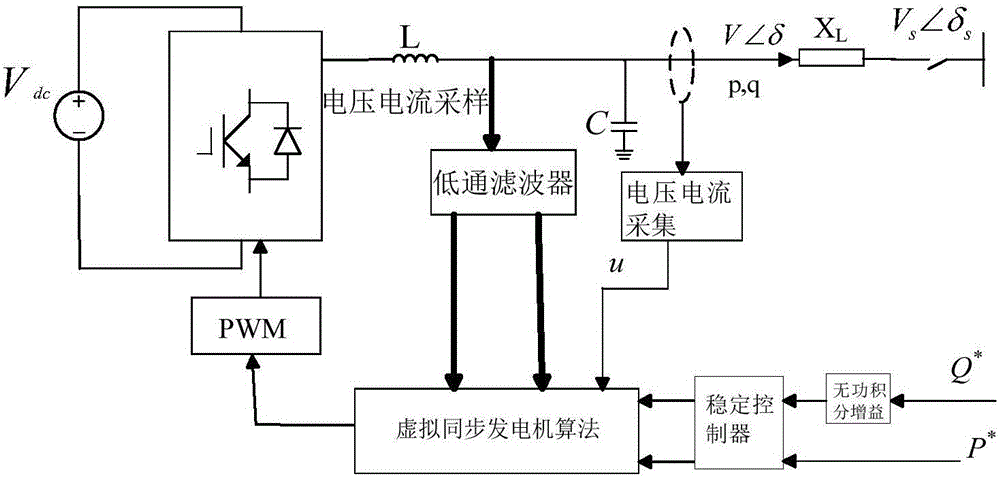
[0038] Such as figure 1 As shown in the figure, the block diagram of the improved low-voltage microgrid droop control is shown.

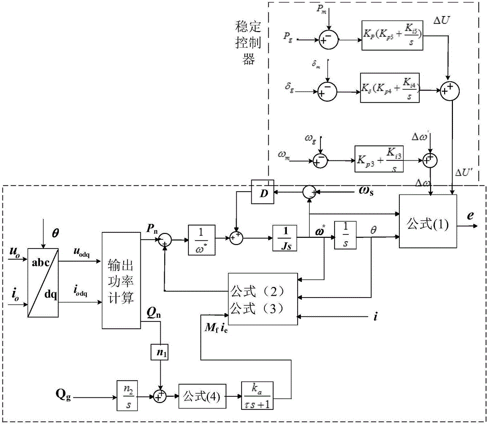
[0039] Such as figure 2 As shown, the figure is the control schematic diagram of the improved low-voltage microgrid droop control, set P T is the mechanical power, P e is the electromagnetic power, J is the moment of inertia of the rotor (kg.m 2 ), ω * is the reference electric angular velocity, D is the constant damping coefficient, e is the induced electromotive force, M f is the maximum inductance between the field winding and the field winding, i e Is the excitation current, θ is the electrical angle of the generator.

[0040] The present invention comprises the following steps:

[0041] A. According to the operating principle of the synchronous generator, the mathematical model of the virtual synchronous generator (VSG) is as follows:

[0042] e = ...


PUM


Abstract

The invention relates to a self-adaptive control method for modes of a low-voltage microgrid. The method comprises the following steps of (1) obtaining power operation parameters of the low-voltage microgrid and constructing a droop control model of the low-voltage microgrid based on a virtual synchronous generator; (2) adding a low-pass filter between a virtual synchronous generator control link and a filter inductor to carry out voltage and current sampling of the filter inductor in the droop control model of the low-voltage microgrid based on the virtual synchronous generator; (3) adding a stability controller between the virtual synchronous generator control link and the reactive power and active power reference value signals while adding a reactive integral gain link between the stability controller and the reactive power reference value signal to obtain a modified droop control model of the low-voltage microgrid; and (4) carrying out mode switching on the low-voltage microgrid according to the modified droop control model of the low-voltage microgrid. In comparison with the prior art, the method has the advantages of disturbance elimination, stable switching, high stability, strong practicability and the like.

Description

technical field [0001] The invention relates to the field of micro-grid operation control strategy wave analysis, in particular to an adaptive control method for a low-voltage micro-grid mode. Background technique [0002] In recent years, with the development of distributed power generation, microgrids containing distributed generation (Distributed Generation, DG) have received more and more attention in the context of energy consumption, energy security and environmental issues. With the access of a large number of DGs, the scale of the microgrid is also increasing, making the operation control method of the traditional power system no longer applicable to the microgrid. The microgrid is a low-voltage power distribution network composed of multiple DGs, energy storage devices, loads and control systems. It can operate in grid-connected mode or in an island mode. This requires the control system to ensure that the two operating modes of the microgrid are smooth. switch. H...

Claims


Application Information

Patent Timeline
Patent Type & Authority Applications(China)
IPC IPC(8): H02J3/00H02J3/38
CPCH02J3/00H02J3/38H02J3/388H02J2203/20Y02P80/14
Inventor 陈甜甜张鹏罗祾
Owner SHANGHAI MUNICIPAL ELECTRIC POWER CO
Why Eureka
Try Eureka