Heat pump type drying device

A drying device and heat pump technology, applied in heating devices, heat pumps, drying, etc., can solve the problems of heat energy loss, low heat energy conversion efficiency, which can only reach about 90%, and achieve the purpose of promoting heating and drying and reducing drying energy consumption , The effect of reducing energy loss

Inactive Publication Date: 2016-08-31
湘西银湘农业科技有限责任公司 +1
View PDF5 Cites 0 Cited by
  • Summary
  • Abstract
  • Description
  • Claims
  • Application Information

AI Technical Summary

Problems solved by technology

The drying process is essentially the process of discharging the moisture in the material. However, almost all existing drying equipment uses direct heating to discharge the moisture in the material in the form of gaseous water. Because the enthalpy of gaseous water is much higher than that of liquid water And the temperature is high, so a large amount of energy is also discharged when the gaseous water is discharged, which inevitably causes a large amount of heat energy loss, which is obviously not in line with my country's current energy...

Method used


Image

  • Heat pump type drying device

Examples


Embodiment Construction

[0018] Now in conjunction with accompanying drawing, the present invention is described in further detail.

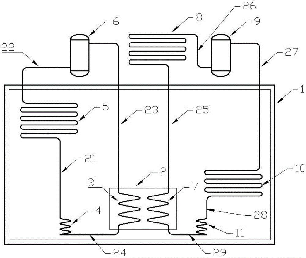
[0019] Such as figure 1 The shown heat pump drying device is isolated from the external environment by the thermal insulation enclosure 1, and the thermal insulation enclosure 1 constitutes a dry working environment, wherein there is a water tank 2, and the spiral coil tube A3 and the spiral coil tube B7 are installed in the water tank 2 and injected An appropriate amount of water submerges the spiral coil; compressor A6, spiral coil A3, capillary A4, coil A5 and pipes 21, 22, 23, and 24 form a group A heat pump cycle dehumidification system; compressor B9, coil B10, capillary B11, The spiral coil tube B7, the outer coil tube 8 and the pipelines 25, 26, 27, 28, 29 form a group B heat pump circulation heating system. The A and B systems work alternately to realize the heat pump cooling in the dry environment to condense and discharge the water vapor, and the heat pump h...


PUM


Abstract

The invention discloses a heat pump type drying device. A water tank is arranged in a heat preserving enclosure; water is injected in the water tank to immerse a spiral coil pipe A and a spiral coil pipe B in the water tank; a compressor A, the spiral coil pipe A, a capillary pipe A, a coil pipe A and relevant pipelines form a heat pump cycle dehumidifying system A; a compressor B, a coil pipe B, a capillary pipe B, the spiral coil pipe B, an outer coil pipe and relevant pipelines form a heat pump cycle heating system B; the system A achieves cooling in the heat preserving enclosure and condensation drainage of vaporous water, and heat released during cooling and condensation of the vaporous water is stored in the water tank; the system B achieves temperature rising in the heat preserving enclosure and the operation of vaporizing water in materials into the heat preserving enclosure and absorbs the heat stored in the water tank by the system A; and the system A and the system B alternately work to achieve evaporation, condensation and drainage of the water in the materials in the heat preserving enclosure and storage and utilization of the heat in the water tank. Compared with an existing gaseous state dehumidifying and drying manner, energy consumption is greatly reduced, and zero emission of refrigerating and dehumidifying heat can be achieved.

Description

technical field [0001] The invention relates to a heat pump drying device. Background technique [0002] Drying device is a very widely used equipment, widely used in biology, medicine, chemical industry, agriculture and other fields. The drying process is essentially the process of discharging the moisture in the material. However, almost all of the existing drying equipment uses direct heating to discharge the moisture in the material in the form of gaseous water. Because the enthalpy of gaseous water is much higher than that of liquid water And the temperature is relatively high, so a large amount of energy is also discharged when the gaseous water is discharged, which inevitably causes a large amount of heat energy loss, which is obviously not in line with my country's current energy-saving and emission-reduction policies. [0003] On the other hand, most of the heating methods of existing drying equipment are direct heating, that is, direct heating by steam or electrici...

Claims


Application Information

Patent Timeline
IPC IPC(8): F26B23/10F25B30/02
CPCF26B23/10F25B30/02
Inventor 银永忠向波
Owner 湘西银湘农业科技有限责任公司
Why Eureka
Try Eureka