Stacking hoister

A hoist and stacking technology, applied in the field of stacking hoist, can solve the problems of poor lifting stability, small contact area, affecting cutting quality, etc., and achieve the effect of stable lifting, small jitter, and improved cutting quality.

Inactive Publication Date: 2016-10-26
成都驿都果业有限责任公司
View PDF4 Cites 2 Cited by
  • Summary
  • Abstract
  • Description
  • Claims
  • Application Information

AI Technical Summary

Problems solved by technology

Since the slider is installed on the lifting column, the contact area is small, the lifting stability is poor, and the accessories installed on the lifting column are light in weight. When the lifting column is lowered to a low position, the vibration is serious, which affects the cutting quality

Method used


Image

  • Stacking hoister
  • Stacking hoister

Examples


Embodiment 1

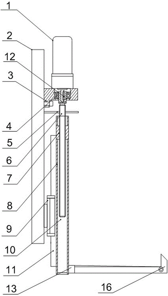
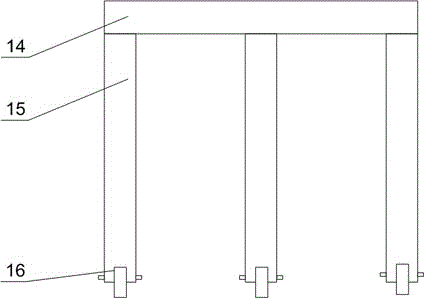
[0022] Such as figure 1 and figure 2 As shown, this includes a fixed plate 2, the fixed plate 2 is installed on the cutting machine, a mounting seat 3 is arranged on the upper end of the fixed plate 2, a motor 1 is arranged on the mounting seat 3, and a linear guide rail is installed at the lower end of the fixed plate 2 11 pairs, the 11 pairs of linear guide rails are connected with a lifting column 8, and a blind hole 10 is opened on the lifting column 8, and also include a lifting screw 6 and a nut 7, and the nut 7 is fixed in the blind hole 10, and the lifting screw 6 One end passes through the nut 7 and is placed in the blind hole 10, the other end of the lifting screw 6 passes through the mounting base 3 and is connected to the output end of the motor 1, and the lifting screw 6 can rotate freely in the mounting base 3 on the lifting column 8. A front fork 13 is installed on the side wall. The front fork 13 is composed of a support rod 14 and three legs 15 arranged side...

Embodiment 2

[0026] Such as figure 1 As shown, in this embodiment, on the basis of Embodiment 1, the linear guide rail 11 pair includes a linear guide rail 11 and a slider 9, and the linear guide rail 11 is arranged on the outer wall of the lifting column 8 close to the fixed plate 2 side, so The slider 9 is fixedly installed on the lower end of the fixed plate 2, and the linear guide rail 11 is slidably arranged on the slider 9. In order to improve the lifting stability of the lifting mechanism, the weight of the installation parts is light and the shaking is serious when the lifting column 8 is lowered to a low position, on the basis of the original transmission mode, the slider 9 of the linear guide rail 11 and the linear guide rail 11 are mutually connected. Change the position, that is, the slider 9 is installed on the fixed plate 2, and the linear guide rail 11 is fixed on the lifting column 8, because the length of the linear guide rail 11 is much longer than that of the slider 9, t...

Embodiment 3

[0028] Such as figure 1 As shown, on the basis of Embodiment 1, the present embodiment is provided with a bearing 4 inside the mounting seat 3, and the lifting screw 6 passes through the bearing 4, and the upper end of the lifting screw 6 has a mounting hole, and the motor 1 The output end is fixed in the installation hole through the flat key 12; it also includes a limit plate 5, the limit plate 5 is installed on the fixed plate 2, and a through hole is opened on the limit plate 5, and the lifting screw rod 6 passes through the through hole. The inner diameter of the through hole is smaller than the outer diameter of the nut 7. The bearing 4 can make the lifting screw 6 reduce the radial vibration of the lifting screw 6 when the motor 1 is just started or turned off or suddenly changes speed, so as to ensure the stability of the lifting screw 6; , the connection between the output end of the motor 1 and the lifting screw 6 is prone to loosening, and the output end of the mot...


PUM


Abstract

The invention discloses a stacking hoister. The stacking hoister comprises a fixed plate, a mounting base is arranged at the upper end of the fixed plate, a motor is arranged on the mounting base, a linear guide rail pair is arranged at the lower end of the fixed plate, and is connected with a hoisting column, a blind hole is formed in the hoisting column, one end of a lifting screw penetrates a nut to be arranged in the blind hole, the other end of the lifting screw penetrates the mounting base to be connected with the output end of the motor, the lifting screw can freely rotate in the mounting base, a front fork is mounted on the side wall of the hoisting column, the front fork is composed of a supporting rod and a plurality of supporting feet, and the multiple supporting feet are arranged on the supporting rod side by side; and during manufacturing, the supporting feet and the supporting rod are forged into a whole, fruit packaging boxes are stacked and stored together and then are hoisted, and stability in the hoisting process can be ensured.

Description

technical field [0001] The invention relates to a cutting machine, in particular to a stacking hoist. Background technique [0002] In the process of mechanical processing, the common methods of plate cutting include manual cutting, semi-automatic cutting machine cutting and CNC cutting machine cutting. Manual cutting is flexible and convenient, but manual cutting has poor quality, large dimensional errors, large material waste, and heavy follow-up processing workload. At the same time, the working conditions are harsh and the production efficiency is low. Among the semi-automatic cutting machines, the profiling cutting machine has better quality of cutting workpieces. Because it uses a cutting mold, it is not suitable for single-piece, small-batch and large-scale cutting; although other types of semi-automatic cutting machines reduce the labor intensity of workers, their functions Simple, only suitable for cutting parts with regular shapes. Compared with manual and semi-a...

Claims


Application Information

Patent Timeline
Patent Type & Authority Applications(China)
IPC IPC(8): B66F7/14B66F7/28B23Q1/25B23Q5/28B23Q5/40
CPCB66F7/14B23Q1/25B23Q5/28B23Q5/40B66F7/28
Inventor 彭超
Owner 成都驿都果业有限责任公司
Why Eureka
Try Eureka