Ultra-short-focus projection lens and laser projection equipment

A technology of projection lens and ultra-short focus, which is applied in the field of projection, can solve the problems of high cost and low manufacturability, and achieve the effect of strong aberration correction ability, high definition, and high quality projection picture

Active Publication Date: 2016-10-26
QINGDAO HISENSE LASER DISPLAY CO LTD
View PDF7 Cites 29 Cited by
  • Summary
  • Abstract
  • Description
  • Claims
  • Application Information

AI Technical Summary

Problems solved by technology

However, there are multiple aspheric or free-form surface mirrors in the design form of this type of projection lens, which has high cost and low manufacturability in the process of processing, manufacturing, and testing.

Method used


Image

  • Ultra-short-focus projection lens and laser projection equipment
  • Ultra-short-focus projection lens and laser projection equipment
  • Ultra-short-focus projection lens and laser projection equipment

Examples


Embodiment 1

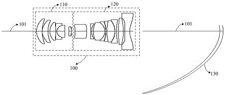
[0051] An embodiment of the present invention provides an ultra-short-focus projection lens, such as Figure 1AAs shown, the ultra-short-focus projection lens includes a refracting mirror group 100 and a reflecting mirror group 130 . The refracting mirror group 100 includes a first lens group 110 and a second lens group 120 , and the reflecting mirror group 130 includes a reflecting mirror, which is placed behind the second lens group 120 . The refracting mirror group 100 and the reflecting mirror group 130 are on the same main optical axis 101 . Wherein, both the first lens group 110 and the second lens group 120 have two aspheric lenses, which have better aberration correction capability.

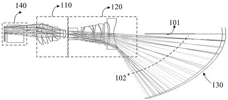
[0052] The schematic diagram of the optical path of the ultra-short-focus projection lens provided in this embodiment is as follows Figure 1B As shown, the image beam output by the optomechanical part 140 passes through the refracting mirror group 100, that is, after being refracted and...

Embodiment 2

[0067] Embodiment 2 of the present invention provides an ultra-short-focus projection lens on the basis of Embodiment 1.

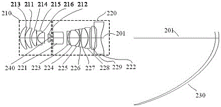
[0068] and specifically, as Figure 2A As shown, along the incident direction of the light beam, the refracting lens group includes: a first lens group 210 and a second lens group 220 in sequence.

[0069] The first lens group 210 and the second lens group 220 are on the same optical axis 201 .

[0070] The first lens group 210 includes at least one spherical lens and two aspheric lenses, and at least one spherical lens is arranged between the two aspheric lenses of the first lens group 210; A lens group 210 corrects the image beam, and sends the corrected image beam to the second lens group 220;

[0071] The second lens group 220 comprises at least one spherical lens and two aspheric lenses, and at least one spherical lens is arranged between the two aspheric lenses of the second lens group; The lens group 220 is used to correct the image beam, and out...

Embodiment 3

[0110] Embodiment 3 of the present invention provides a laser projection device, which can be applied to the ultra-short-focus projection lens of Embodiment 1 or Embodiment 2 above.

[0111] Specifically, such as Figure 3A as shown, Figure 3A It is a schematic diagram of the architecture of a laser projection device, which can be a laser theater or a laser TV, or other laser projection equipment, such as Figure 3A As shown, it includes a laser light source 30 , an optical machine 31 , an ultra-short-throw projection lens 32 , and a projection screen 33 . The laser light source 30 provides an illumination beam for the optical machine 31, and the laser light source 30 can be a mixed light source composed of a single-color or two-color laser light source and a fluorescent light source, or a three-color laser light source. The optical machine 31 is used to modulate the illumination light beam according to the image processing signal to form an image light beam. Specifically, ...


PUM


Abstract

The invention discloses an ultra-short-focus projection lens, and belongs to the technical field of projection. The ultra-short-focus projection lens comprises a refractor group and a reflector group. After an image beam passes through the refractor group, the first imaging is carried out between the refractor group and the reflector group, and is reflected by the reflector group to a projection screen to form second imaging. The refractor group comprises a first lens group and a second lens group, wherein the first and second lens groups are respectively provided with two aspherical lenses. The reflector group comprises a first reflector which is disposed behind the second lens group. The refractor group and the reflector group are located on the same primary optical axis. The offset of an image formed by the second imaging relative to the primary optical axis is 140%-150%. The projection lens provided by the invention can achieve the projection of a short-focus large-size image, has a better capability of aberration correction, and can improve the projection imaging quality.

Description

technical field [0001] The invention relates to the field of projection technology, in particular to an ultra-short-focus projection lens and laser projection equipment. Background technique [0002] With the improvement of science and technology, projection imaging systems are more and more widely used in people's work and life, such as education, office, home or entertainment. Among them, the ultra-short-throw projection can effectively shorten the projection distance of the projector and project a large-size picture, which is favored by consumers. [0003] The projection lens is a key component to realize projection. In practical applications, the optical system of the projection lens will produce aberrations due to processing technology, assembly and other reasons, such as distortion, astigmatism, field curvature, and coma. Design challenges that must be faced. [0004] In order to effectively overcome aberrations, there are currently three lens design methods, namely ...

Claims


Application Information

Patent Timeline
Patent Type & Authority Applications(China)
IPC IPC(8): G02B13/18G02B13/24G03B21/28
CPCG02B13/00G02B13/18G02B13/24G02B26/0816G02B26/0875G03B21/28
Inventor 阴亮李晓平
Owner QINGDAO HISENSE LASER DISPLAY CO LTD
Why Eureka
Try Eureka