
Insulated hanging ladder for equipotential work
An equipotential and operational technology, which is applied to ladders, overhead lines/cable equipment, buildings, etc., can solve the problems that operators cannot control the direction of rotation, the potential transfer rod cannot be hung, and the time of riding the elevator is long, etc., to ensure that Work safety, ease of work safety, and ride comfort improvement effects
- Summary
- Abstract
- Description
- Claims
- Application Information
AI Technical Summary
Problems solved by technology
Method used
Image

Examples
Embodiment 1
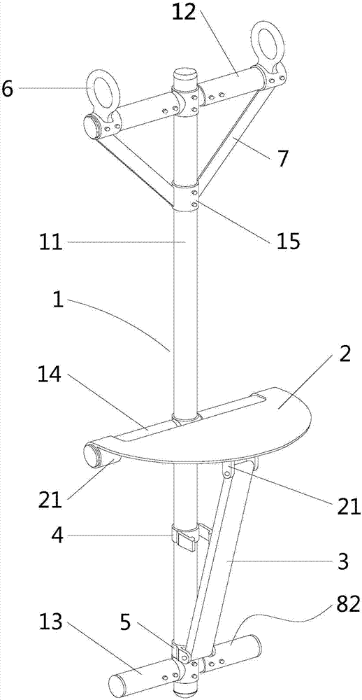
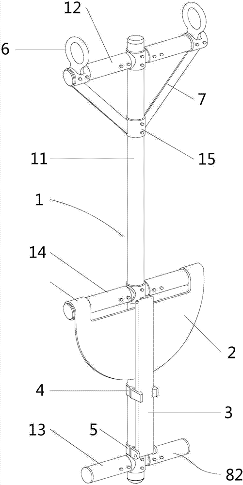
[0037] like figure 1 , 2 As shown, the special insulation hanging ladder for equipotential work provided by the embodiment of the present invention includes a base frame 1, a stool 2 for riding and a support rod 3 for supporting the stool 2, and one side of the stool 2 is rotatably connected to the The base frame 1, one end of the support rod 3 is rotatably connected to the base frame 1 and is located below the connection between the stool and the base frame, and the other end of the support rod 3 cooperates with the stool board 2 to fix and support the stool board during use.
[0038] The base frame 1 is in the shape of a "king" or a "non" and includes a vertical rod 11, a top rod 12 arranged at the top of the vertical rod, a bottom rod 13 arranged at the bottom of the vertical rod, and a bottom rod between the top and the bottom of the vertical rod. The cross bar 14 , in this embodiment, the cross bar 14 is arranged at the middle part of the vertical bar 11 or at a position...
Embodiment 2
[0053] The difference between this embodiment and the above-mentioned embodiment 1 is that the thickness of the stool board 2 is relatively large, and the bottom surface of the stool board is provided with a draw-in groove on the side away from the base frame 1 to cooperate with the top of the support rod 3. When the support rod 3 is in use The supporting stool 2 is fixed through the cooperation of the top end and the draw-in groove.
PUM
 Abstract
Description
Claims
Application Information