Tool-free operation spare part combination and cabinet for radar system

A radar system, tool-free technology, applied in the direction of electrical equipment shell/cabinet/drawer, electrical components, casing/cabinet/drawer parts, etc., can solve the problem of cumbersome assembly and disassembly process, so that it is not easy to lose parts , quick disassembly and assembly, simple operation

Active Publication Date: 2021-09-28
BEIJING INST OF RADIO MEASUREMENT
View PDF6 Cites 0 Cited by
  • Summary
  • Abstract
  • Description
  • Claims
  • Application Information

AI Technical Summary

Problems solved by technology

[0003] The technical problem to be solved by the present invention is that the spare parts of the existing radar system are mostly con...

Method used


Image

  • Tool-free operation spare part combination and cabinet for radar system
  • Tool-free operation spare part combination and cabinet for radar system
  • Tool-free operation spare part combination and cabinet for radar system

Examples


Embodiment 1

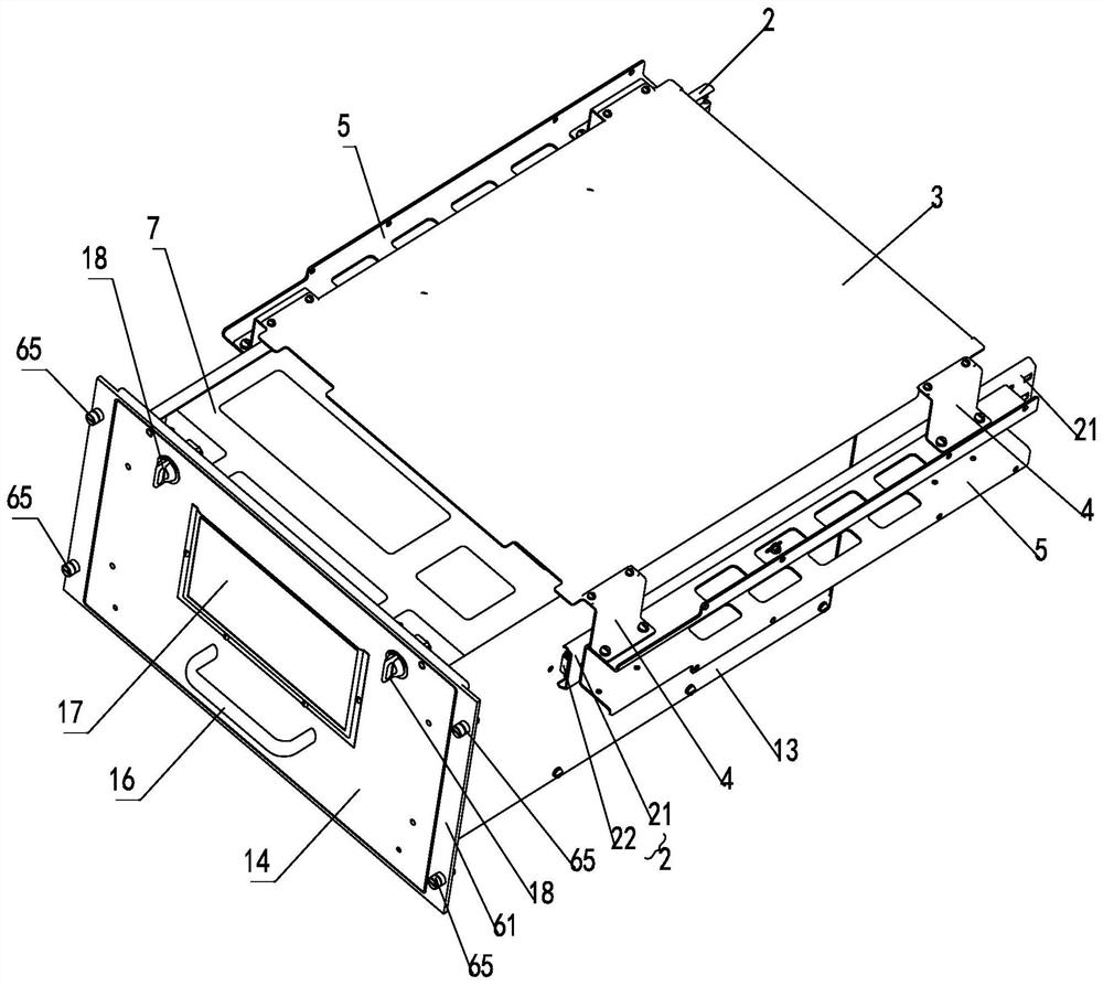
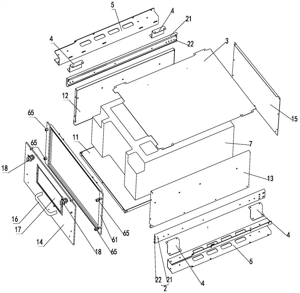
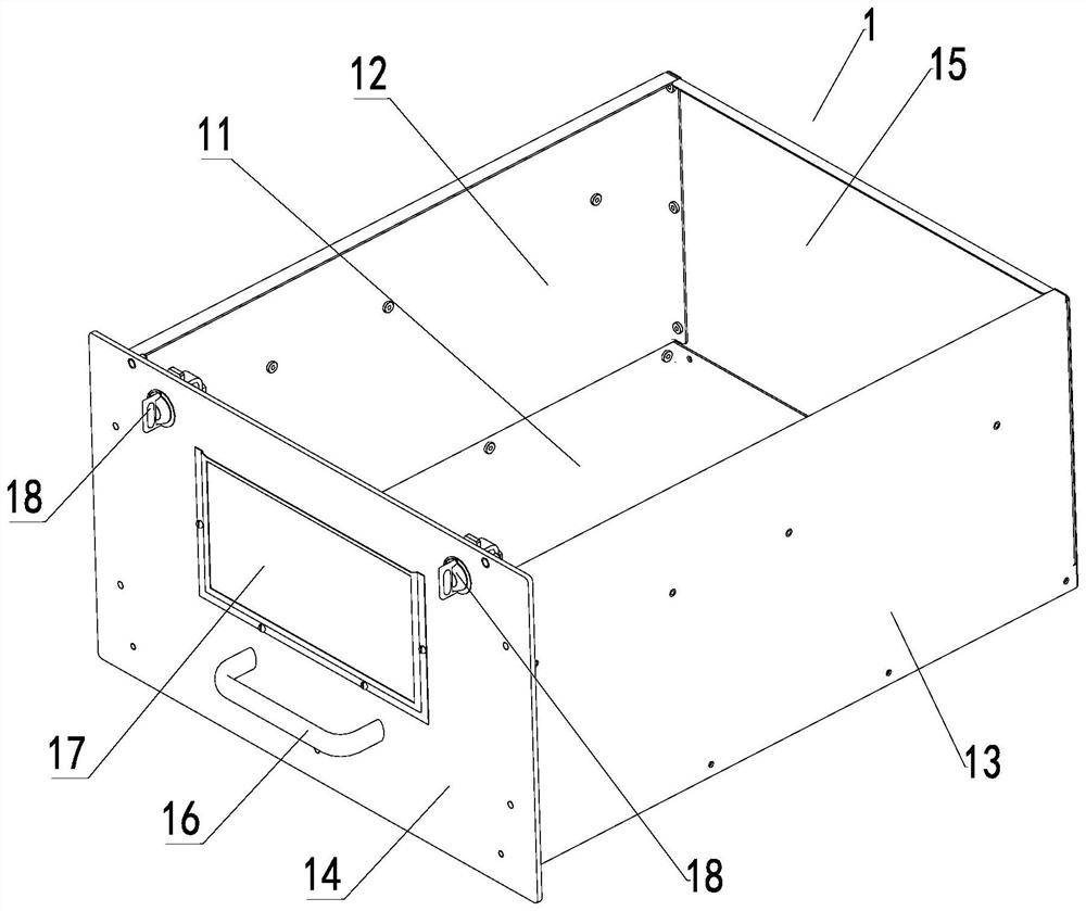
[0039] Such as Figure 1 ~ Figure 4 As shown, a tool-less operation spare parts combination of this embodiment includes a main structure 1, a guide rail 2, a top cover 3 and a support assembly, the main structure 1 is a box structure with an open upper end, and the top cover 3, guide rails 2 are connected to both sides through support components, and the two side walls of the main structure 1 are respectively connected to the guide rails 2 on both sides of the top cover 3.

[0040] The guide rail 2 of this embodiment can adopt a two-stage guide rail or a multi-stage guide rail.

[0041] A preferred solution of this embodiment is, as Figure 1 ~ Figure 3 As shown, the guide rail 2 of this embodiment is a three-stage guide rail, the two sides of the top cover 3 are respectively connected to the outer guide rails 21 of the three-stage guide rail through support components, and the two side walls of the main structure 1 are connected to the three-stage guide rail respectively. T...

Embodiment 2

[0053] Such as Image 6 As shown, a cabinet for a radar system in this embodiment includes a cabinet body 6 and the spare parts combination, and the supporting components on both sides of the spare parts combination are respectively connected in the cabinet body 6 .

[0054] Such as Image 6 As shown, the front side of the cabinet body 6 in this embodiment is provided with a plurality of push-pull openings 63, and the push-pull openings 63 are provided with a panel frame 61, and the panel frame 61 is installed on the On the cabinet body 6. Specifically, the outer edges can be respectively set on both sides of the panel frame 61, and one or more captive screws are respectively set on the outer edges of the two sides, and the captive screws are set on the panel frame. The frame is completely disassembled for assembly.

[0055] Such as Figure 4 with Figure 5 As shown, the outer surface of the panel frame 61 in this embodiment is provided with a circle of limiting grooves 6...


PUM


Abstract

The invention relates to a tool-free operation spare part combination and a cabinet for a radar system. The spare part combination comprises a main body structure, guide rails, a top cover and supporting assemblies, wherein the main body structure is a box body structure with an open upper end, the two sides of the top cover are connected with the guide rails through the supporting assemblies respectively, and the two side walls of the main body structure are connected with the guide rails on the two sides of the top cover respectively. The cabinet for the radar system comprises a cabinet body and the spare part combination, and the supporting assemblies on the two sides of the spare part combination are connected into the cabinet body. The spare part combination can be disassembled and assembled without tools and can be pulled out from the top cover by means of the guide rails, rapid disassembly and assembly can be achieved, the vehicle-mounted requirement can be met, and the application requirements of low cost, high reliability and the like are met. The spare part combination in the cabinet does not need to be disassembled and assembled by a tool, so that the style unification with the radar system is ensured, tools are not needed, and the application requirements of low cost, high reliability and the like are met.

Description

technical field [0001] The invention relates to the related technical field of electronic equipment structure design, in particular to a tool-less operation spare parts combination and a cabinet for a radar system. Background technique [0002] The spare parts combination is mainly used to store spare parts, accessories, independent units, tools and other items, which play the role of storage and protection, and are an indispensable part of the whole system. The combination of spare parts is different from the combination of functional units, the installation and use requirements are lower, and the frequency of assembly and disassembly is higher. Commonly used spare parts combination design, with sheet metal parts as the main structure, the top cover is fastened with screws, nuts, and washers, and the panel is installed on the cabinet with non-falling screw components, but this method uses tools, and the operation efficiency is low. And the standard parts are easy to be sca...

Claims


Application Information

Patent Timeline
IPC IPC(8): H05K5/02H05K7/14
CPCH05K7/14H05K5/0217H05K5/023
Inventor 王思佳刘剑赵德斌王海宁李亦健
Owner BEIJING INST OF RADIO MEASUREMENT
Why Eureka
Try Eureka