Ratchet type insulation wire clamping pincers

A wire clamp and ratchet-type technology, which is applied in the field of ratchet-type insulating wire clamps, can solve the problems of the wearability of the rotary mechanism, frequent maintenance and replacement, live accidents, etc., and achieve the effect of reliable live clamping

Active Publication Date: 2016-12-14
STATE GRID CORP OF CHINA +1
View PDF4 Cites 21 Cited by
  • Summary
  • Abstract
  • Description
  • Claims
  • Application Information

AI Technical Summary

Problems solved by technology

The problem with the above structure is that: on the one hand, the movement of the screw nut is a fine-tuning movement after all. It seems that the stroke of an opening and closing action of the jaws is relatively short, but in fact, when the insulating rod rotates relative to the screw nut of the fixed block, it often needs to be adjusted. The corresponding insulating rod rotates multiple times; not to mention the low efficiency, it is obviously extremely difficult to operate when the outdoor temperature is low in winter and the rod body freezes, etc.
On the other hand, due to the existence of the thread pitch, the insulating rod used as the screw rod will inevitably have mechanical loosening or even sliding teeth, which will lead to electrification accidents, which greatly increases the unsafety of high-voltage live wire construction
In addition, since the insulating rod as the screw rod needs to be continuously rotated, and the block chuck as the jaw must maintain a static clamping relative to the drain wire, this will inevitably require a combination of the block chuck and the matching insulating rod. In order to solve the above problems, a slewing mechanism is installed between them, which further complicates the structure, and at the same time causes the wear and tear of the slewing mechanism and the need for frequent maintenance and replacement.

Method used


Image

  • Ratchet type insulation wire clamping pincers
  • Ratchet type insulation wire clamping pincers
  • Ratchet type insulation wire clamping pincers

Examples


Embodiment Construction

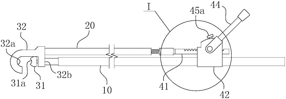
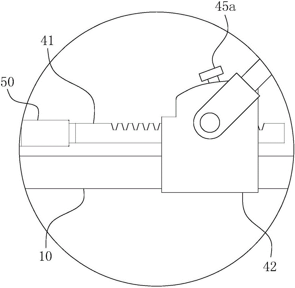
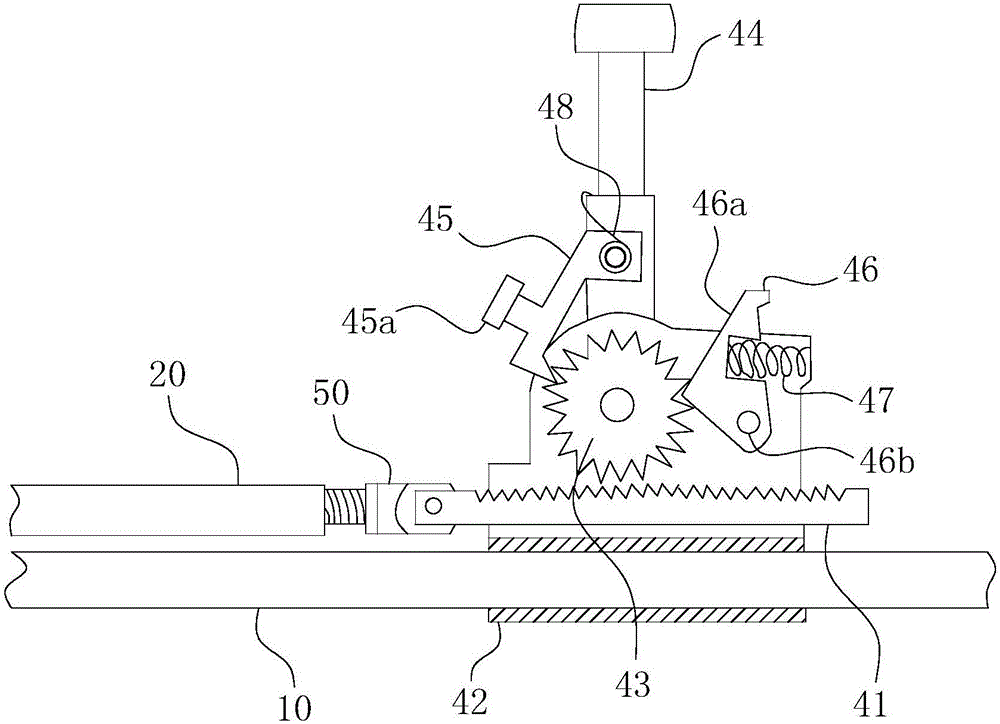
[0037] For ease of understanding, combined here Figure 1-4 Concrete structure of the present invention and work flow are described further as follows:

[0038] In practical application, the present invention is mainly divided into three parts: clamping part, insulating rod part and ratchet assembly. Among them, the clamping part is composed of two chucks, such as Figure 1-2 As shown, the upper hook-shaped chuck 31 is a movable chuck, and the lower block-shaped chuck 31 is a static chuck. The two chucks are directly fixed on the top ends of the two insulating rods arranged in parallel in a screw-in manner. Through the movement of the movable chuck along the direction parallel to the insulating rod, it will move towards and away from the static chuck to form the jaw clamping function of the two. The specific clamping principle relies on clamping the movable chuck and the static chuck on the drainage wire, and through the operation of the following ratchet assembly, the mova...


PUM


Abstract

The invention belongs to the field of electric power construction tools and in particular relates to ratchet type insulation wire clamping pincers used for high-voltage electrified wire construction. The ratchet type insulation wire clamping pincers comprise a first insulation rod and a second insulation rod. A block type chuck and a hook-like chuck are respectively arranged on top ends of the two insulation rods. The ratchet type insulation wire clamping pincers also comprise a ratchet assembly. The ratchet assembly comprises a gear part, a back support and a locking piece. A ratchet, a handle part and a pawl are arranged in the back support. The locking piece comprises a top block and a press spring. The top block is in the same direction with the unidirectional locking direction of the pawl relative to the unidirectional locking direction of the ratchet. The top block is arranged on a moving route of the handle part or the pawl. A matching surface used for matching the handle part or the pawl is arranged on the top block. The pressing force direction, relative to the matching surface, of the handle part or the pawl is opposite to the elastic restoring force direction of the press spring. The pincers is highly practical and convenient and quick to use; and high safety during working is ensured while high-efficient hot-line work is ensured.

Description

technical field [0001] The invention belongs to the field of electric construction tools, and in particular relates to a ratchet-type insulating wire clamp used for construction of high-voltage live wires. Background technique [0002] Due to the needs of electric power construction, for example, if a transformer on the ground is to be removed, the live drain wire connected to the high-voltage power line must be cut off from a high place at first, so that the transformer is cut off, commonly known as a fire break. At present, the fire-off operation of the drainage wire is completed by the coordination and cooperation of the wire clamp and the wire cutter. The construction method is: the electric power construction personnel hold the wire clamp and stand on the ground under the drainage wire, and keep a certain distance from the drainage wire. distance. Put the top clamp head of the wire clamp close to the drain wire, and operate the wire clamp to close the jaws to clamp the...

Claims


Application Information

Patent Timeline
Patent Type & Authority Applications(China)
IPC IPC(8): H02G1/02
CPCH02G1/02
Inventor 李君孟明明阳江明傅志国
Owner STATE GRID CORP OF CHINA
Why Eureka
Try Eureka