Multifunctional electronic lock body

An electronic lock, multi-functional technology, applied in the field of electronic locks, can solve the problems of complex structure, inconvenient door locking, unable to meet the installation requirements of anti-theft doors, etc., and achieve the effect of simple operation

Inactive Publication Date: 2016-05-18
CHENGDU PUTAISHENG TECH
View PDF5 Cites 3 Cited by
  • Summary
  • Abstract
  • Description
  • Claims
  • Application Information

AI Technical Summary

Problems solved by technology

Fully mechanical anti-theft locks are becoming less and less suitable for modern people's life characteristics due to the inconvenience of locking the door, and have been gradually replaced by electronic anti-theft locks; however, the original electronic lock body is generally thick, wide and large It meets the installation requirements of some anti-theft doors (especially thin doors), and at the same time, the damage to the door is relatively large; and the existing electronic lock has a too complicated structure in the control of handling the 360° rotation of the handle to open the door lock, and it is difficult to deal with mechanical keys. no good way

Method used


Image

  • Multifunctional electronic lock body
  • Multifunctional electronic lock body
  • Multifunctional electronic lock body

Examples


Embodiment 1

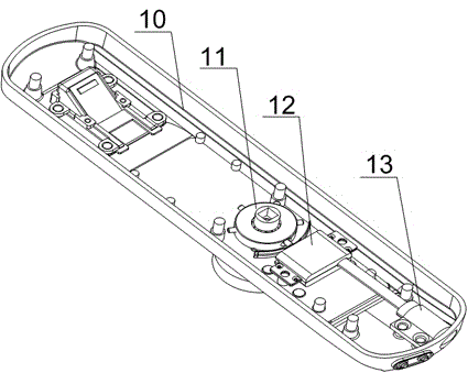
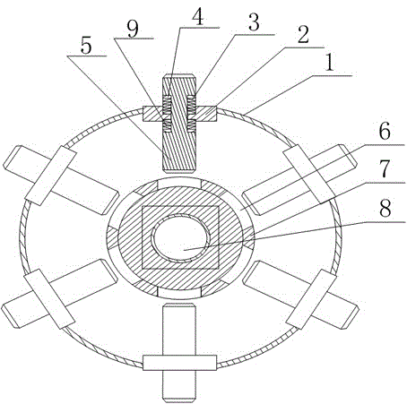
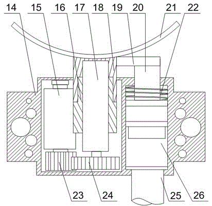
[0027] Such as Figure 1~Figure 4 As shown, this embodiment includes a clutch 11 and a driver 12. The clutch 11 includes a circular box body 1, a plurality of pins 5, and a rotating core 7 fixed in the middle of the box body 1. The middle part of the rotating core 7 has a The through hole 8 for the handle shaft to pass through has a rectangular groove 4 on the two side walls at one end of the pin 5, and a plurality of supports matching the pin 5 are installed on the peripheral wall of the box body 1. Block 2, a small hole is opened in the middle of the support block 2, and the other end of the pin 5 passes through the small hole and is placed in the box body 1, and a flange is provided on the inner wall of the small hole, and the inner wall of the flange is in contact with the rectangular groove 4. Bottom contact, a plurality of limit holes 6 coaxial with the pin 5 are opened on the outer wall of the rotating core 7; it also includes a spring A3 and a spring B9 arranged in the r...


PUM


Abstract

The invention discloses a multifunctional electronic lock body, which comprises a clutch and a driver; the clutch comprises a box body, a plurality of pins and a rotating core; a through hole for a handle rotating shaft to penetrate is formed in the middle part of the rotating core; a rectangular groove is formed in each of two side walls of one end of each pin; a circumferential wall of the box body is provided with a plurality of supporting blocks separately matched with the pins; a small hole is formed in the middle part of each supporting block; the other end of each pin penetrates through the corresponding small hole and is arranged in the box body; the inner wall of each small hole is provided with flanges, and the inner wall of each flange is in contact with the bottom of the corresponding rectangular groove; a plurality of spacing holes coaxial with the pins are formed in the outer wall of the rotating core; one end of each of springs A is fixed to the upper end face of the corresponding flange, and the other end of each spring A is fixed to the inner wall of one end of the corresponding rectangular groove; one end of each of springs B is fixed to the lower end face of the corresponding flange; and the other end of each spring B is fixed to the inner wall of the other end of the corresponding rectangular groove. The multifunctional electronic lock body disclosed by the invention is capable of realizing electronic unlocking and mechanical unlocking simultaneously, is simple to operate when handling a mechanical emergency, and is convenient and practical.

Description

technical field [0001] The invention relates to the field of electronic locks, in particular to a multifunctional electronic lock body. Background technique [0002] The current anti-theft lock body is divided into a full mechanical anti-theft lock body and an electronic intelligent anti-theft lock body. Fully mechanical anti-theft locks are becoming less and less suitable for modern people's life characteristics due to the inconvenience of locking the door, and have been gradually replaced by electronic anti-theft locks; however, the original electronic lock body is generally thick, wide and large It meets the installation requirements of some anti-theft doors (especially thin doors), and at the same time, the damage to the door is relatively large; and the existing electronic lock has a too complicated structure in the control of handling the 360° rotation of the handle to open the door lock, and it is difficult to deal with mechanical keys. There is no good way. Conten...

Claims


Application Information

Patent Timeline
Patent Type & Authority Applications(China)
IPC IPC(8): E05B47/06
CPCE05B47/0692
Inventor 李奕廷
Owner CHENGDU PUTAISHENG TECH
Why Eureka
Try Eureka