Grinding bar type grinding machine

A technology of milling machine and sand bar, which is applied in the direction of solid separation, separation of solid from solid by air flow, and grain processing, etc. The effect of whitening efficiency

Inactive Publication Date: 2017-01-04
HUBEI BISHAN MACHINERY CO LTD
View PDF8 Cites 7 Cited by
  • Summary
  • Abstract
  • Description
  • Claims
  • Application Information

AI Technical Summary

Problems solved by technology

But, when emery roller 14 is grinding grain, its surface carborundum also can wear and tear, and the diameter of emery roller will become smaller, and the space of milling room becomes larger, and the storage material in milling chamber becomes more, and grain contacts sand The probability of roller 14 decreases, resulting in poor whitening effect. At this time, the entire emery roller 14 needs to be replaced
[0004] Among them, the iron roller mill such as Figure 2A and Figure 2B As shown, the iron roller mill mainly arranges convex ribs symmetrically in the axial direction on the surface of the iron roller 15, and the blocking strip 17.1 set on the regular polygonal screen 17 makes the grains roll continuously in the grinding chamber. Squeeze and friction, so that the skin of the grain grains will fall off, but because the grains are rubbed away from each other, the pressure in the milling chamber will be relatively high, causing the grains to be easily broken, resulting in more broken grains

Method used


Image

  • Grinding bar type grinding machine
  • Grinding bar type grinding machine
  • Grinding bar type grinding machine

Examples


Embodiment Construction

[0032] The present invention will be further described in detail below in conjunction with the accompanying drawings and specific embodiments.

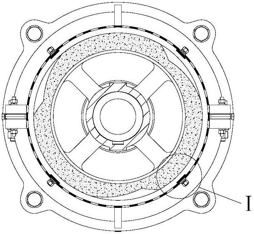
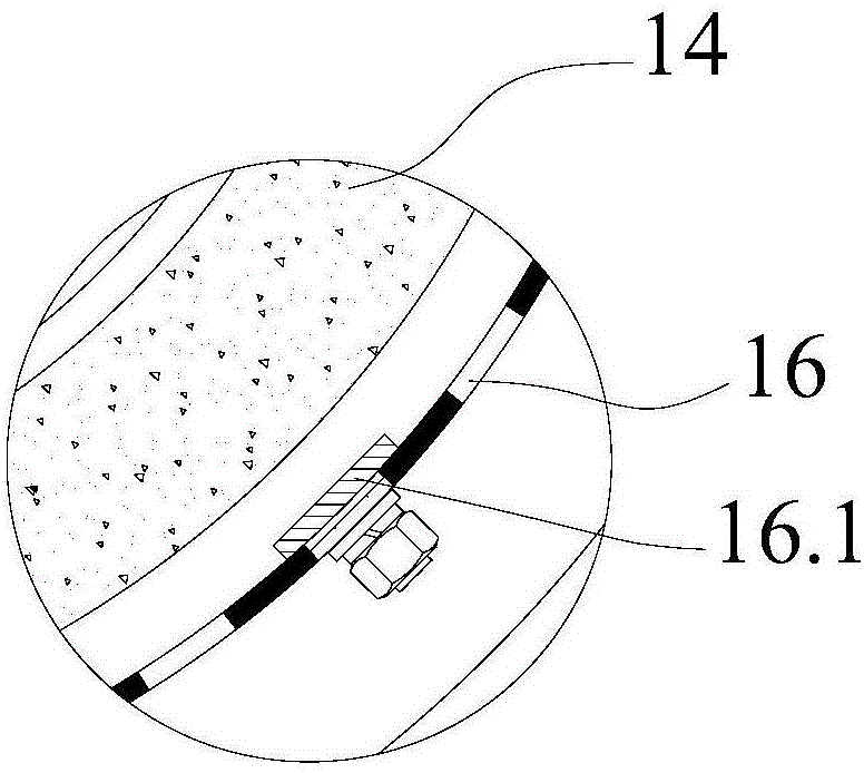
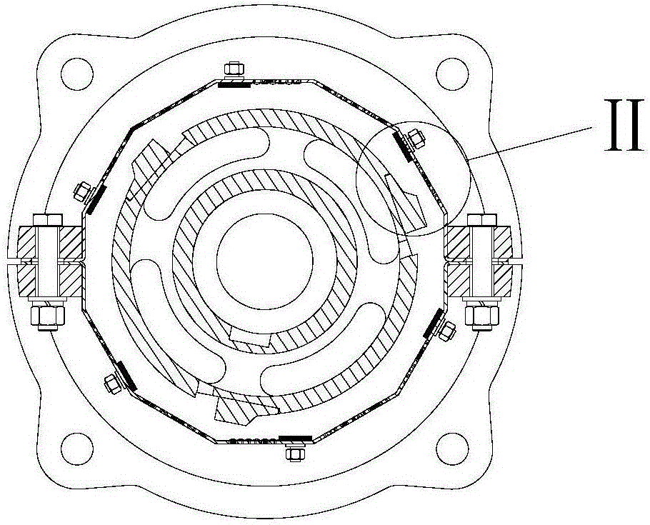
[0033] A sand bar mill, such as image 3 As shown, it includes a frame 1 and a bearing seat 3 installed on the frame 1. A main shaft 4 is vertically installed on the bearing seat 3. The main shaft 4 is connected to the motor 7 in a transmission manner. The upper part of the main shaft 4 is covered with a grinding roller 10. The periphery of the roller 10 is provided with a sieve cylinder 12 matched with the grinding roller 10, a grinding chamber is formed between the grinding roller 10 and the sieve cylinder 12, and the top of the grinding roller 10 passes through the feeding roller 13.1 and the discharge part 13. Connected, the bottom end of the grinding roller 10 is connected with the feeding part 5 through the screw propeller 8, and the periphery of the screen cylinder 12 is provided with a screen frame cover 9, and the screen fram...


PUM


Abstract

The invention discloses a grinding bar type grinding machine. The grinding bar type grinding machine comprises a machine frame and a main shaft, wherein the main shaft is in transmission connection with a motor; a grinding roll is sheathed on the upper part of the main shaft; a screen cylinder is arranged at the periphery of the grinding roll and is matched with the grinding roll; a grinding chamber is formed between the grinding roll and the screen cylinder; the grinding roll comprises a roll body, a plurality of grooves of the roll body are arranged on the outer surface of the roll body along the axial direction, a first grinding bar is fixedly arranged in each groove of the roll body, a convex strip of the roll body is formed between the two grooves of the roll body, and an air ventilating hole is formed in each convex strip of the roll body along the axial direction, and is communicated with the main shaft; the screen cylinder comprises a screen frame body, screen plates and second grinding bars, groove plates are fixedly arranged on the screen frame body, and are provided with grooves, each second grinding bar is fixedly arranged in the corresponding groove, and each screen plate is arranged at the gap between the two groove plates. The grinding bar type grinding machine has the advantages that by adopting the grinding roll and the screen cylinder with the structures, the generation of crushed grains is reduced, and the whitening rate is improved; by utilizing the grinding bars for multiple times, the investment cost of equipment is reduced.

Description

technical field [0001] The invention belongs to the field of grain processing equipment, and in particular relates to a sand bar mill. Background technique [0002] The mill is the key equipment in the field of grain processing. In the mill, the grain is loaded into the mill from the feeding part, and enters the milling chamber composed of the milling roller and the sieve drum under the action of the screw propeller. The grain Grinding and peeling each other in the milling chamber, the milled grains flow out from the discharge nozzle, and the hulls of the grains are ground into bran, and the bran is discharged through the sieve under the suction of the external fan to complete the milling of the grain. [0003] At present, there are many kinds of mills used in the market, which are divided into two types according to the different grinding rollers: sand roller mills and iron roller mills. Among them, sand roller mills, such as Figure 1A and Figure 1B As shown, the emery r...

Claims


Application Information

Patent Timeline
Patent Type & Authority Applications(China)
IPC IPC(8): B02B3/04B02B7/00B07B7/06
CPCB02B3/04B02B7/00B07B7/06
Inventor 周润根李红梅
Owner HUBEI BISHAN MACHINERY CO LTD
Why Eureka
Try Eureka