Lateral support pressing mechanism for numerical control bending machine

A technology of bending machine and supporting pressure, which is applied in the field of forging, can solve the problems of height adjustment of the supporting pressure mechanism, affecting the bending accuracy of the workpiece, time-consuming and labor-intensive problems, and achieve the effect of improving the accuracy of the supporting pressure and improving production efficiency

Inactive Publication Date: 2017-02-15
黄石华强数控机床有限公司
View PDF0 Cites 1 Cited by
  • Summary
  • Abstract
  • Description
  • Claims
  • Application Information

AI Technical Summary

Problems solved by technology

[0003] The technical problem to be solved by the present invention is: in order to solve the problems existing in the above-mentioned background technology, an improved lateral support mechanism for a CNC bending machine is provided to solve the problem of manual bending during the bending process of the workpiece. Supporting and fixing the workpiece is not only time-consuming and laborious, but also the instability of manual operation can easily affect the bending accuracy of the workpiece. Due to the different specifications of the workpiece, the height of the traditional supporting mechanism cannot be adjusted according to the specification of the workpiece, which is very inconvenient to use. question

Method used


Image

  • Lateral support pressing mechanism for numerical control bending machine
  • Lateral support pressing mechanism for numerical control bending machine

Examples


Embodiment Construction

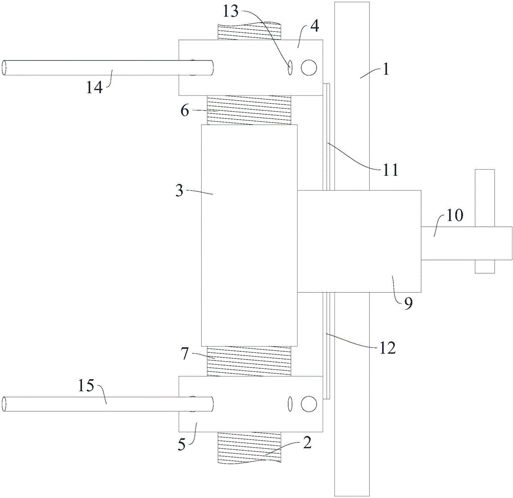
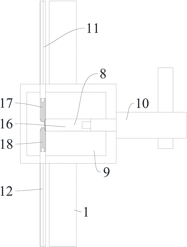
[0013] The present invention is described in further detail now in conjunction with accompanying drawing. These drawings are all simplified schematic diagrams, which only illustrate the basic structure of the present invention in a schematic manner, so they only show the configurations related to the present invention.

[0014] figure 1 and figure 2 The shown lateral support mechanism for a CNC bending machine includes a fixed bracket 1 fixed on one side of the lower die of the CNC bending machine and a vertical screw located between the fixed bracket 1 and the lower die of the CNC bending machine 2. The main cylinder body 3 is covered with the vertical screw rod 2, and the main cylinder body 3 is fixedly connected to the surface of the fixed bracket 1. The fixing method can be fixed by bolts or detachable fixed connection in other ways. The main cylinder body 3 The upper end is provided with an upper fixed mounting seat 4, and the lower end of the main cylinder body 3 is p...


PUM


Abstract

The invention relates to the technical field of forging, in particular to a lateral support pressing mechanism for a numerical control bending machine. The mechanism comprises a fixed bracket fixed on one side of a lower mold of the numerical control bending machine, and a longitudinal lead screw positioned between the fixed bracket and the lower mold of the numerical control bending machine; the longitudinal lead screw is coated with a main cylinder; an upper fixed mounting base is arranged at the upper end of the main cylinder; and a lower fixed mounting base is arranged at the lower end of the main cylinder. The lateral support pressing mechanism for the numerical control bending machine respectively performs fixed connection for an upper pressing rod and a lower support rod through threaded connection of the upper and lower ends of the main cylinder with the upper fixed connecting base and the lower fixed connecting base with internal thread connecting holes on the surfaces, respectively adjusts gaps between the upper and lower fixed connecting bases through linkage of a control rod on a control base with a transmission rod, can freely adjust the height according to the workpiece thickness, further improves the support pressing precision, and promotes the production efficiency.

Description

technical field [0001] The invention relates to the technical field of forging, in particular to a lateral support mechanism for a numerically controlled bending machine. Background technique [0002] The CNC bending machine controls the up and down movement of the oil cylinder through the CNC system, thereby driving the mold installed on the slider to move up and down, and squeezes with the lower mold installed on the workbench to realize the bending of the workpiece. During the bending process, the workpiece is mainly supported and fixed manually, which is not only time-consuming and laborious, but also the instability of manual operation can easily affect the bending accuracy of the workpiece. Due to the different specifications of the workpiece, the height of the traditional supporting mechanism cannot It is very inconvenient to adjust according to the workpiece specification. Contents of the invention [0003] The technical problem to be solved by the present inventi...

Claims


Application Information

Patent Timeline
Patent Type & Authority Applications(China)
IPC IPC(8): B21D11/22
CPCB21D11/22
Inventor 王松王刚徐文李昌新
Owner 黄石华强数控机床有限公司
Why Eureka
Try Eureka