Non-contact pantograph-catenary contact force measuring method and device

A non-contact, measurement method, applied in the direction of measuring the force of change in optical properties of materials when they are stressed, can solve the problems of incomplete reflection of elastic force, disadvantageous cost savings, etc., and achieve efficient extraction of light strip displacement. Accuracy, high pressure accuracy, the effect of reducing equipment cost

Pending Publication Date: 2021-01-12
CHENGDU TANGYUAN ELECTRICAL APPLIANCE
View PDF1 Cites 2 Cited by
  • Summary
  • Abstract
  • Description
  • Claims
  • Application Information

AI Technical Summary

Problems solved by technology

However, this method requires four sets of targets and measuring equipment to complete the pantograph-catenary contact force measurement, which is not conducive to saving costs, and the paired targets are located at the upper and lower ends of the internal spring of the bow head, and the measured elastic force does not fully reflect the longitudinal direction of the bow head. Elastic force produced by the spring

Method used


Image

  • Non-contact pantograph-catenary contact force measuring method and device
  • Non-contact pantograph-catenary contact force measuring method and device
  • Non-contact pantograph-catenary contact force measuring method and device

Examples


Embodiment 1

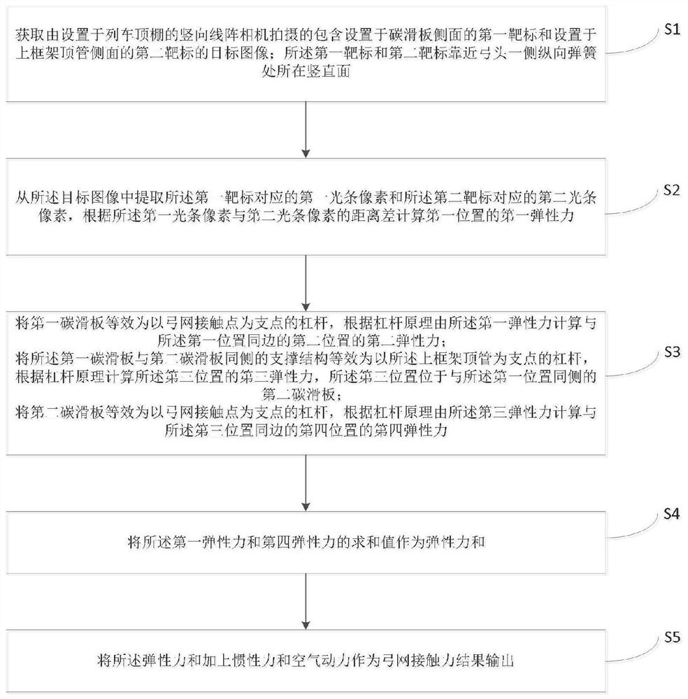
[0050] This embodiment provides a non-contact pantograph-catenary contact force measurement method, such as figure 1 mentioned, including:

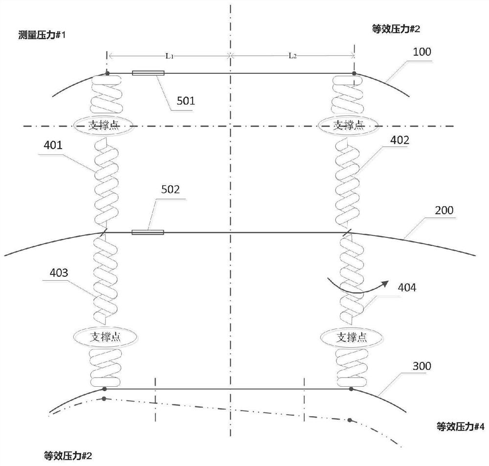
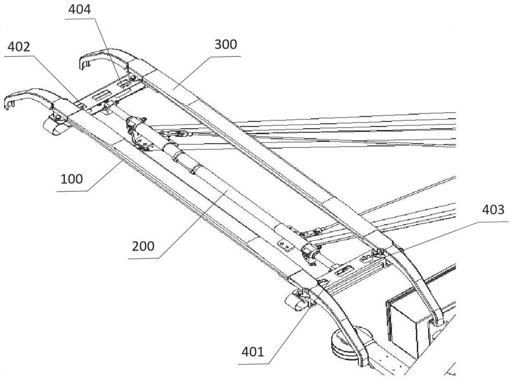
[0051] Step S1, obtain the target image including the first target 501 arranged on the side of the first carbon skateboard 100 and the second target 502 arranged on the side of the upper frame top tube 200 taken by the vertical line array camera arranged on the roof of the train; The vertical plane where the first target 501 and the second target 502 are close to the longitudinal spring 401 on the side of the bow head; there is no strict requirement for the setting positions of the first target 501 and the second target 502, only restricting them to be on the same vertical plane , so that the line-scan camera can capture the light strip images corresponding to the first target 501 and the second target 502 at the same time, through a qualified and accurate calibration process, the connection position between the two ends of the slide plat...

Embodiment 2

[0072] Embodiment 2 provides a non-contact pantograph-catenary contact force calculation device, such as Figure 7 shown, including:

[0073] The target image acquisition module is used to acquire the target image that includes the first target arranged on the side of the first carbon slide plate and the second target arranged on the side of the top pipe of the upper frame taken by the vertical line array camera arranged on the roof of the train; Both the first target and the second target are arranged on a vertical plane near the longitudinal spring on one side of the bow head;

[0074] a light bar pixel extraction module, configured to extract a first light bar pixel corresponding to the first target and a second light bar pixel corresponding to the second target from the target image;

[0075] A first elastic force calculation module, configured to calculate the first elastic force at the first position according to the distance difference between the first light bar pixel...


PUM


Abstract

The invention relates to the field of rail transit pantograph-catenary relationship detection, in particular to a non-contact pantograph-catenary contact force measurement method and device. The method comprises the following steps: acquiring a target image comprising a first target arranged on the side surface of a carbon slide plate and a second target arranged on the side surface of a top tubeof an upper frame; extracting a first light bar pixel corresponding to the first target and a second light bar pixel corresponding to the second target from the target image, and calculating a first elastic force of a first position according to a distance difference between the first light bar pixel and the second light bar pixel; calculating a second elastic force of a second position on the same side as the first position according to the lever principle and the first elastic force; summing the first elastic force and the second elastic force, and adding inertia force and aerodynamic forceto serve as bow net contact force. Compared with conventional contact pressure sum calculation and non-contact pressure sum calculation of multiple sets of targets, the method has the advantage that the equipment cost is remarkably reduced.

Description

technical field [0001] The invention relates to the field of pantograph-catenary relationship detection in rail transit, in particular to a non-contact pantograph-catenary contact force measurement method and device. Background technique [0002] The electric locomotive obtains electric energy through the sliding contact between the pantograph slide plate and the catenary wire. When the moving pantograph passes through the relatively static catenary, the catenary is disturbed by external force, so the contact between the pantograph and the catenary There is a dynamic interaction between the two systems, and the pantograph-catenary system produces a specific form of vibration. When the vibration is severe, it can cause the pantograph slide plate to be out of contact with the contact wire, forming an off-line, generating arcs and sparks, accelerating the insulation damage of electrical appliances, causing electromagnetic interference to communication, and more seriously, direc...

Claims


Application Information

Patent Timeline
Patent Type & Authority Applications(China)
IPC IPC(8): G01L1/24
CPCG01L1/24
Inventor 张金鑫李想熊昊睿敬斌黄鹏秦朋
Owner CHENGDU TANGYUAN ELECTRICAL APPLIANCE
Why Eureka
Try Eureka