An abrasive flow ultra-precision machining device

A technology of ultra-precision machining and abrasive flow, which is applied in the direction of abrasive feeding device, used abrasive processing device, metal processing equipment, etc. Affect workpiece processing accuracy and other issues, to achieve the effect of ensuring processing efficiency and processing accuracy, improving processing accuracy, and ensuring processing accuracy and efficiency

Inactive Publication Date: 2017-02-22
CHANGCHUN UNIV OF SCI & TECH
View PDF5 Cites 0 Cited by
  • Summary
  • Abstract
  • Description
  • Claims
  • Application Information

AI Technical Summary

Problems solved by technology

[0004] Abrasive flow is a viscous abrasive containing abrasive particles, which is suitable for inner cavity processing, because its non-fixed shape determines the complexity of the processing mechanism. At present, scholars at home and abroad mainly focus on the viscosity, working pressure, abrasive particles and other factors Research on the processing method of abrasive flow has gradually developed some devices that use abrasive flow to perform ultra-precision machining of workpieces. However, the abrasive flow spray head of the current abrasive flow processing device generally uses a spring to give the spray head a certain pressure, but spring pressure is used. Although some pressure sensors are used, the way of applying force is not smooth, and the pressure will be greatly affected by the failure of the spring, which will affect the machining accuracy of the workpiece, and the nozzle. The pressure of the abrasive flow is only adjusted by the pressure pump, and the adjustment effect is limited, and the end of the abrasive flow spray head lacks a flow blocking device, which reduces the impact of the abrasive flow and lowers the processing efficiency

Method used


Image

  • An abrasive flow ultra-precision machining device

Examples


Embodiment Construction

[0019] The present invention will be described in detail below with reference to the accompanying drawings. It should be understood, however, that the accompanying drawings are provided only for a better understanding of the present invention, and they should not be construed to limit the present invention.

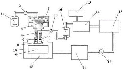
[0020] like figure 1 As shown, the present invention provides an abrasive flow ultra-precision machining device, which includes a pneumatic cylinder 1, a closed box 3, a pressure plug 4, a pressure head 5, an abrasive flow jet polishing nozzle 6 and a recovery tank 10, the pressure plug One end of the pressure plug 4 is arranged in the airtight box 3, the upper end of the pressure plug 4 forms a closed space with the upper space of the airtight case 3, the lower end of the pressure plug 4 is connected with the pressure head 5, and the lower end of the pressure head 5 An external thread is provided, the upper end of the abrasive jet polishing nozzle 6 is provided with an ...


PUM


Abstract

The invention provides an abrasive particle flow ultra-precision machining device. Injection pressure and speed of abrasive particle flows are adjusted by adjusting threads between a pressure head and an abrasive particle flow injection polishing nozzle, and pressure is provided for a sealed box through a pneumatic cylinder, so that pressure is applied to the pressure head through a pressure plug. According to the abrasive particle flow ultra-precision machining device, the pneumatic cylinder for replacing a spring applies pressure to the pressure head so that accuracy of pressure of the abrasive particle flow injection polishing nozzle to a work-piece can be effectively improved, the abrasive particle flow machining accuracy is improved, and ultra-precision machining is achieved; meanwhile, concentration of abrasive particles in the abrasive particle flows is monitored and controlled in real time, so that machining accuracy and efficiency are guaranteed; Injection pressure and speed of the abrasive particle flows are adjusted by adjusting the threads between the pressure head and the abrasive particle flow injection polishing nozzle, and a pressure-maintaining flow stopping part is arranged at the tail end of the abrasive particle flow injection polishing nozzle so that the machining efficiency can be effectively improved. By means of the abrasive particle flow ultra-precision machining device, both machining efficiency and ultra-precision machining accuracy can be guaranteed.

Description

technical field [0001] The invention relates to the technical field of precision machining, in particular to an abrasive particle flow ultra-precision machining device, which belongs to the technical field of ultra-precision machining. Background technique [0002] In the field of mechanical processing, there are many precision finishing methods in addition to traditional mechanical methods, including ultrasonic polishing, chemical polishing, electrochemical polishing, and electrochemical-mechanical composite processing. Abrasive flow machining is a rapidly developed precision finishing method. One of them has been widely used in the aviation and military industry, textile machinery, steam turbines, molds and hydraulic machinery industries. [0003] Abrasive flow ultra-precision machining technology is a newest machining method. It uses abrasive flow medium (a flowable mixture mixed with abrasive grains) to flow over the surface to be processed by the workpiece under pressur...

Claims


Application Information

Patent Timeline
Patent Type & Authority Patents(China)
IPC IPC(8): B24C3/32B24C7/00B24C9/00B24B31/116B24B57/00B24B57/02
CPCB24B31/116B24B57/00B24B57/02B24C3/32B24C7/00B24C9/00
Inventor 李俊烨张心明张若妍王德民刘建河许颖
Owner CHANGCHUN UNIV OF SCI & TECH
Why Eureka
Try Eureka