Industrial robot

Inactive Publication Date: 2005-09-22
FANUC LTD
View PDF10 Cites 54 Cited by
  • Summary
  • Abstract
  • Description
  • Claims
  • Application Information

AI Technical Summary

Benefits of technology

[0009] The present invention provides an inexpensive articulated type industrial robot of a simple structure in which multiple joint devices are connected in series to each other, wherein a speed reducer having one-stage speed reducing structure, the speed reduc

Problems solved by technology

In this connection, it can be considered that vibration tends to occur in the case where the eccentric rotation ty

Method used


Image

  • Industrial robot
  • Industrial robot
  • Industrial robot

Examples


Embodiment Construction

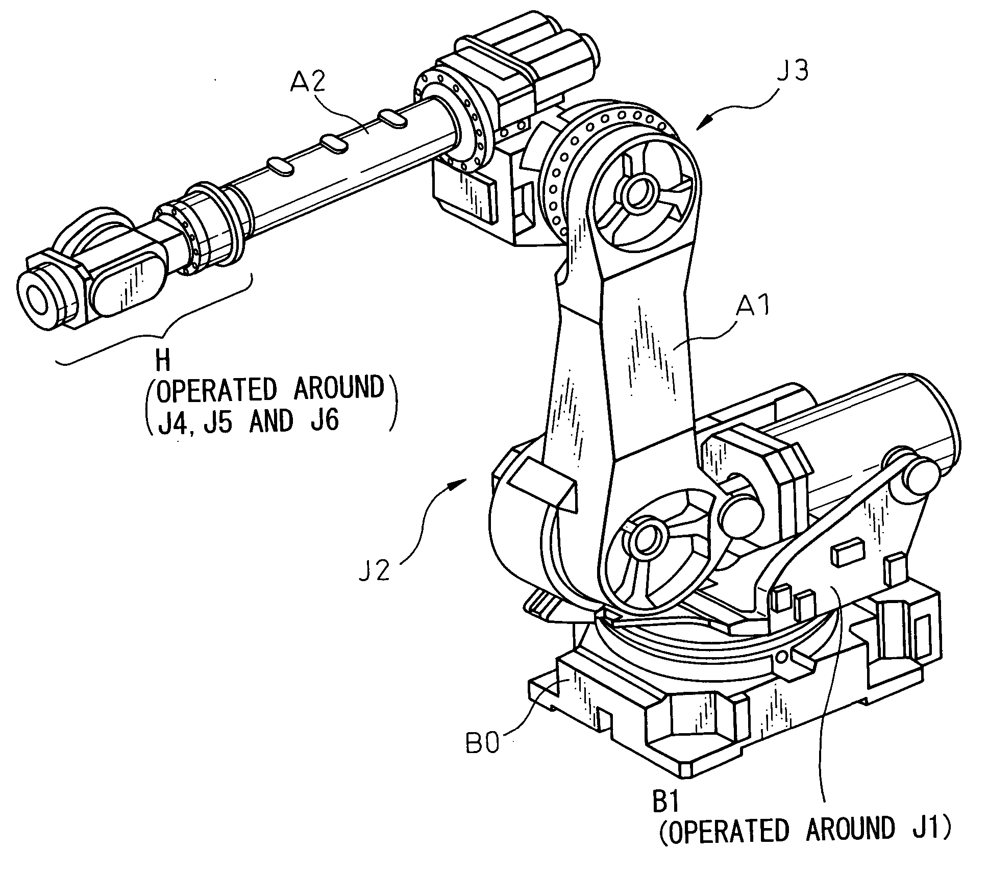
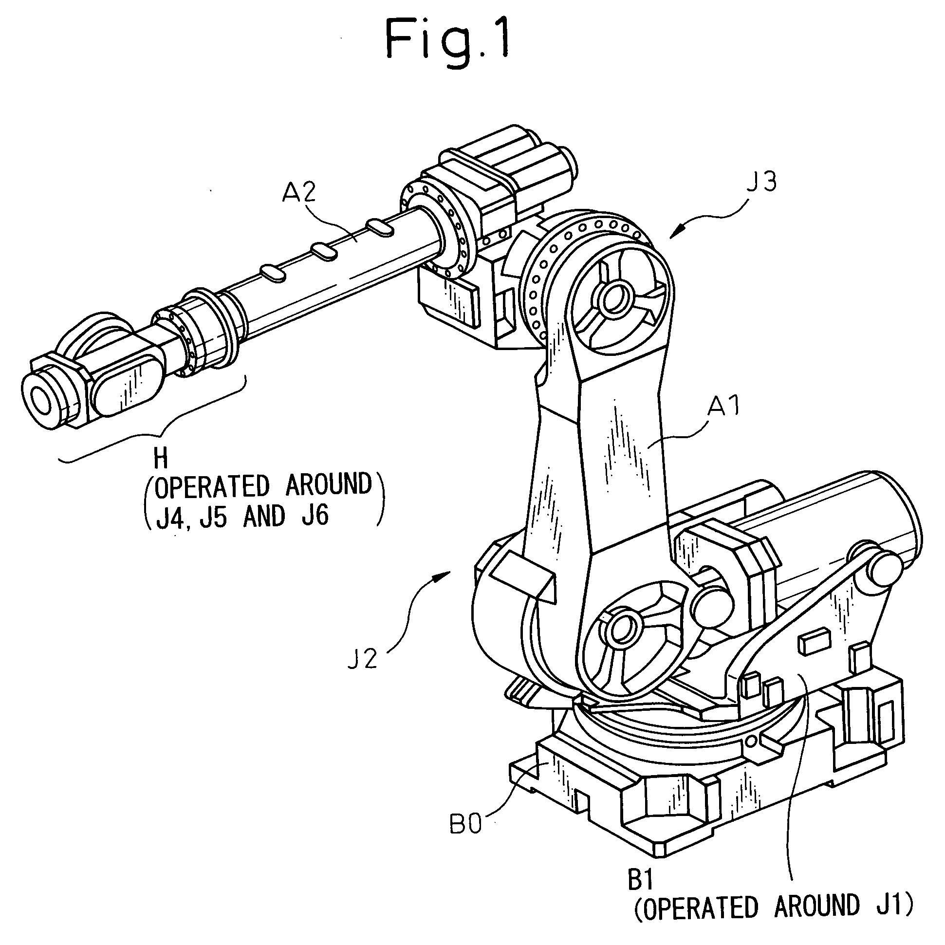
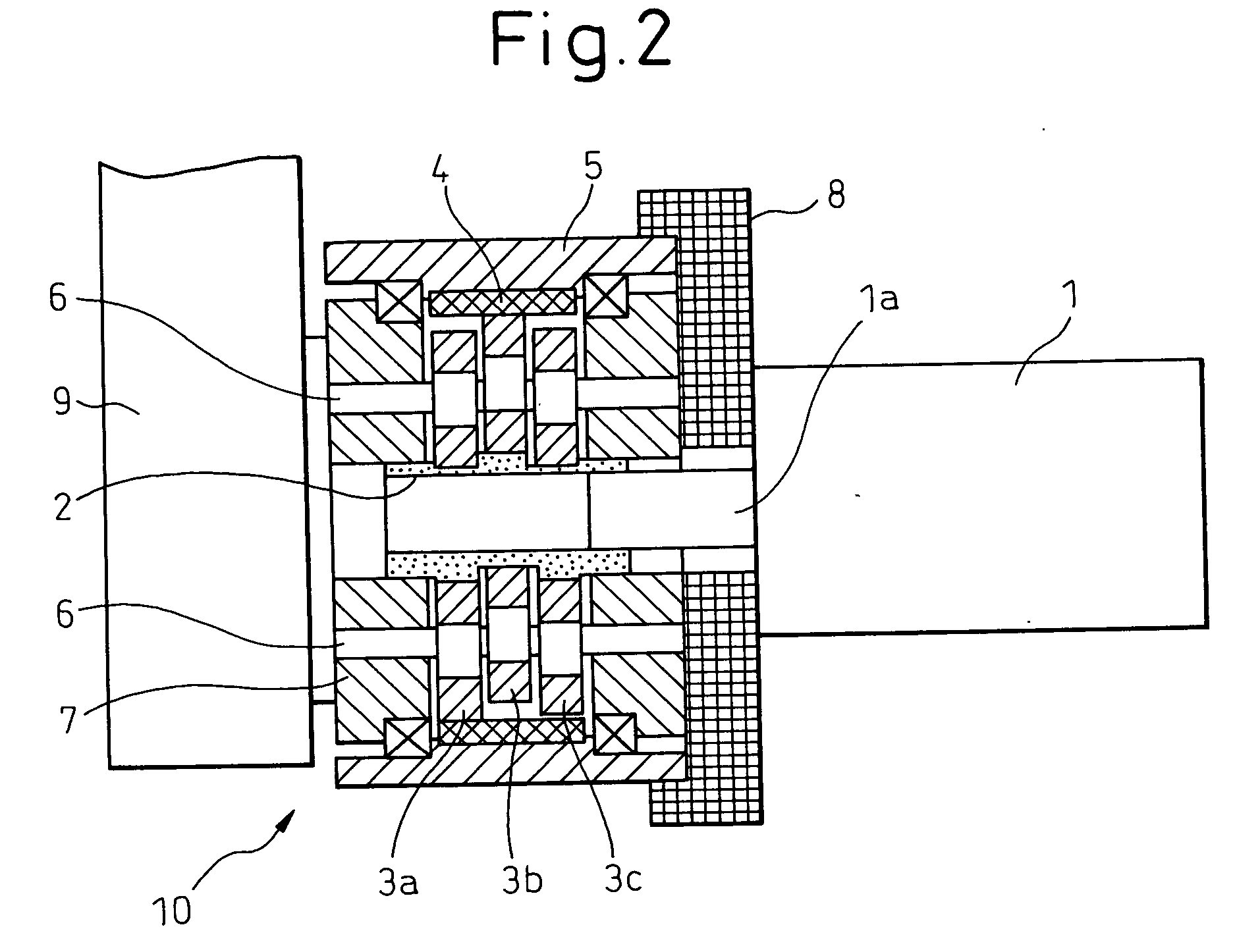
[0021] Referring to FIGS. 1 and 2, an embodiment of the present invention will be explained below. First of all, referring to FIG. 1, the appearance of a robot to which the present invention is applied is exemplarily shown in the perspective view. As shown in this drawing, the robot is an articulated type robot of six axes including: a base B0; a rotary base B1 operated around axis J1; a lower arm A1 operated around axis J2; an upper arm A2 operated around axis J3; and a wrist unit H operated around the three axes (J4 to J6) of the wrist unit so that the wrist unit H can be moved with a three-degrees-of-freedom. In this embodiment, the joint structure of the present invention is applied to the link combinations of the robot rotary base B1, the lower arm A1 and the upper arm A2.

[0022] Needless to say, “the two adjoining links” included in these three links are “the rotary base B1 and the lower arm A1” and “the lower arm A1 and the upper arm A2”, and the joint for relatively rotating...


PUM


Abstract

A joint structure is employed for an articulated type robot in which a speed reducer of one-stage speed reducing structure and a servo motor are directly connected to each other for the joint of the rotary base B1 and the lower arm A1 and for the joint of the lower arm A1 and the upper arm A2. The input shaft 2 of the speed reducer 10 directly connected to the output shaft of the servo motor 1 attached to the first member 8 (B1/A2) is a crank shaft composing a cam, and the external gears 3a, 3b, 3c are meshed with the cam surfaces. When the servo motor 1 is driven and the input shaft 2 is rotated, the external gears 3a, 3b, 3c are eccentrically revolved and rotated while the external gears 3a, 3b, 3c are meshed with the internal gear 4 provided inside the case 5 of the speed reducer 10. The rotation is taken out by a plurality of pin members 6 engaged to the external gears 3a, 3b, 3c and transmitted to the output shaft 7 of the speed reducer 10. Therefore, the second member 9 (A1) is relatively pivoted with respect to the first member 8. Due to the foregoing, the robot structure in which a plurality of joint devices for connecting the adjoining links via the speed reducer are connected in series to each other can be simplified.

Description

BACKGROUND OF THE INVENTION [0001] 1. Field of the Invention [0002] The present invention relates to an industrial robot. More particularly, the present invention relates to an industrial robot having an arm structure using a rotary joint mechanism to rotate adjoining links, by a servo motor, via a speed reducing mechanism of a speed reducer. [0003] 2. Description of the Related Art [0004] In general, a joint structure of an industrial robot is provided with a speed reducer. As the reduction ratio of the speed reducer is high, a speed reducer, such as Cyclo Speed Reducer (registered trade mark) or RV Speed Reducer (registered trade mark), in which an eccentric rotation type planetary differential reduction gear mechanism is employed, is widely used. For example, the mechanism eccentric rotation type planetary differential reduction gear speed reducer referred to as a Cyclo Speed Reducer (registered trade mark) includes: an eccentric body shaft which is also the input shaft of the sp...

Claims


Application Information

Patent Timeline
IPC IPC(8): B25J17/00B25J9/10F16H1/32
CPCB25J9/102Y10T74/20305F16H1/32
Inventor NIHEI, RYOOKADA, TAKESHISHIMADA, NAOKI
Owner FANUC LTD
Why Eureka
Try Eureka