Method of drilling a hole through Co2 laser directly

A laser drilling and direct technology, applied in laser welding equipment, removing conductive materials by chemical/electrolytic methods, welding equipment, etc., can solve the problems of poor precision, high cost, consumption of dry film and etching potion, etc., to achieve The effect of improving accuracy, saving consumption, saving process and time

Inactive Publication Date: 2006-04-19
WUS PRINTED CIRCUIT (KUNSHAN) CO LTD
View PDF0 Cites 57 Cited by
  • Summary
  • Abstract
  • Description
  • Claims
  • Application Information

AI Technical Summary

Problems solved by technology

[0011] 1. The cost is high: copper windows (conformal) need to be opened, after image transfer and etching process, dry film and etching potion are consumed;
[0012] 2. The accuracy is poor: the accuracy is the sum of film accuracy (within 0.5mil), copper window alignment accuracy (within 2mil) and laser drilling accuracy (within 1mil)

Method used


Image

  • Method of drilling a hole through Co2 laser directly
  • Method of drilling a hole through Co2 laser directly
  • Method of drilling a hole through Co2 laser directly

Examples


Embodiment Construction

[0039] The present invention will be further described below in conjunction with the accompanying drawings and embodiments.

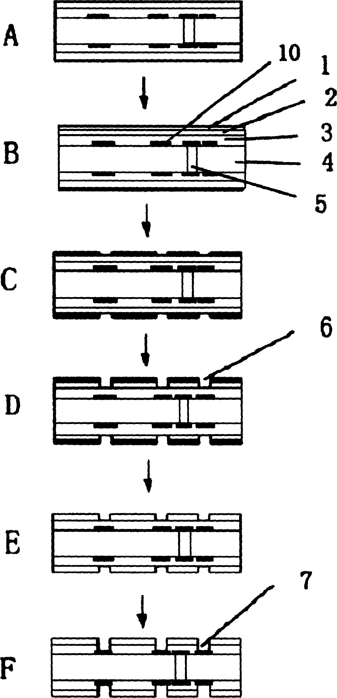
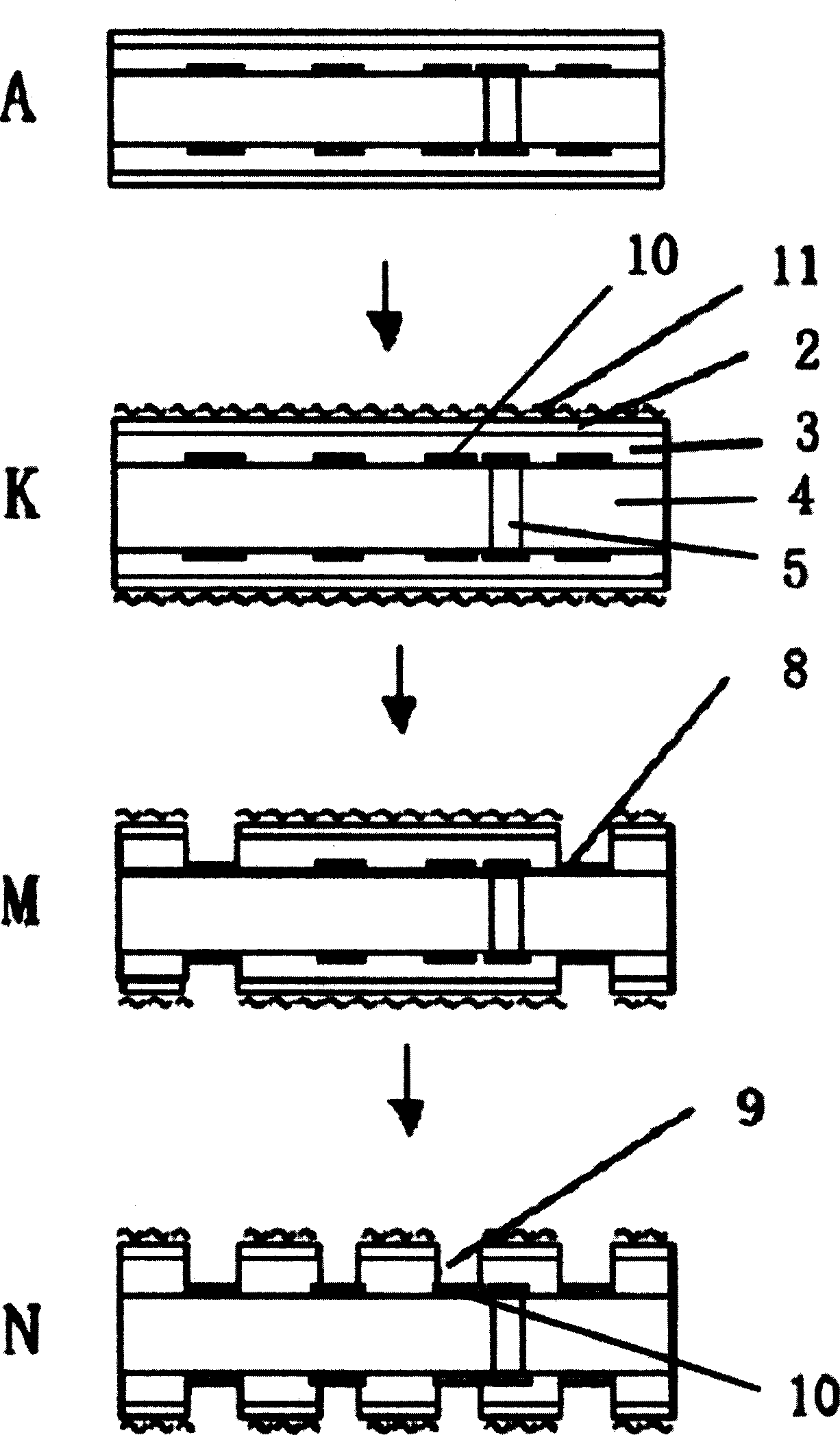
[0040] The present invention operates through the following methods, taking the first-order laser drilling (1+n+1) as an example:

[0041] 1) Make positioning points on the sub-outer layer: during the image transfer process of the sub-outer layer (ie, the outermost layer of the core board), design and manufacture positioning points for processing the microholes in the board on the four corners;

[0042] 2) Oxidation of the surface of the target pad layer before lamination: only browning treatment (normal operating conditions) can be used to improve the bonding force between the copper foil surface and the resin surface, and at the same time, it is convenient to grab the positioning point;

[0043] 3) Lamination of prepreg and copper foil: RCC (adhesive copper foil) or LDP (laser cloth) is used for the prepreg (pre-preg), (these are two commonly used bui...


PUM


Abstract

Drilling method of carbon dioxide laser includes steps: preparing locating point on layer next to the outer layer; before pressfitting added layer, browning oxidizing surface of target bonding pad; after pressfitting added layer, milling location hole / polishing edge, washing surface under high pressure; browning front surface of copper, thinning and coursing the surface before drilling hole by layer; first time to drill hole by laser; positioning film perforation by using plate location hole in original etching method for making window of copper, burning through copper foil and resin above the locating point on layer next to the outer layer so as to expose the locating point; second time to drill hole by laser; using the exposed locating point as position fixing to make micro hole inplate; washing surface under high pressure to remove browning layer after drill hole. The invention saves dry film and etching liquid, and raises process precision.

Description

technical field [0001] The invention belongs to the technical field of printed circuit board (PCB) manufacturing, and relates to a method for directly performing laser drilling by using a CO2 (carbon dioxide) laser drilling machine. Background technique [0002] In the existing manufacturing process of PCB printed circuit boards, if high-density interconnection boards are to be made, it is necessary to laminate the build-up layer on the core board with the circuit already prepared, and then use laser drilling on the build-up layer to match the target pad ( That is, the microholes aligned with the existing circuit layer disc pattern on the core board. The existing laser drilling method usually adopts the traditional etching copper window method (conformal) process, that is, firstly cover the dry film on the board surface, and then use the image transfer method to image the dry film, after exposure, development, etching, etc. , Glue removal and other processes, etch off the c...

Claims


Application Information

Patent Timeline
Patent Type & Authority Applications(China)
IPC IPC(8): H05K3/06B23K26/38B23K26/382
Inventor 杨志清
Owner WUS PRINTED CIRCUIT (KUNSHAN) CO LTD
Why Eureka
Try Eureka