Non-contact pantograph-catenary contact force measurement system based on double three-dimensional targets

A measurement system and contact force technology, which is applied in the measurement of the change force of the optical properties of the material when it is stressed, can solve the problems of difficult to accurately extract the target light strip, affect the pressure measurement accuracy, and save costs, and achieve High pressure accuracy, reduced equipment cost, and the effect of eliminating torsional characteristics

Pending Publication Date: 2021-01-15
CHENGDU TANGYUAN ELECTRICAL APPLIANCE
View PDF1 Cites 1 Cited by
  • Summary
  • Abstract
  • Description
  • Claims
  • Application Information

AI Technical Summary

Problems solved by technology

However, this method still has the following deficiencies: four sets of targets and measuring equipment are required to complete the pantograph-catenary contact force measurement, which is not conducive to saving costs; the paired targets are located at the upper and lower ends of the internal spring of the bow head, and the measured elastic force is not complete. Reflect the elastic force generated by the longitudinal oblique spring of the bow head; the measurement uses a flat target, and it is difficult to accurately extract the target light strip under complex light field conditions, which will affect the pressure measurement accuracy

Method used


Image

  • Non-contact pantograph-catenary contact force measurement system based on double three-dimensional targets
  • Non-contact pantograph-catenary contact force measurement system based on double three-dimensional targets
  • Non-contact pantograph-catenary contact force measurement system based on double three-dimensional targets

Examples


Embodiment 1

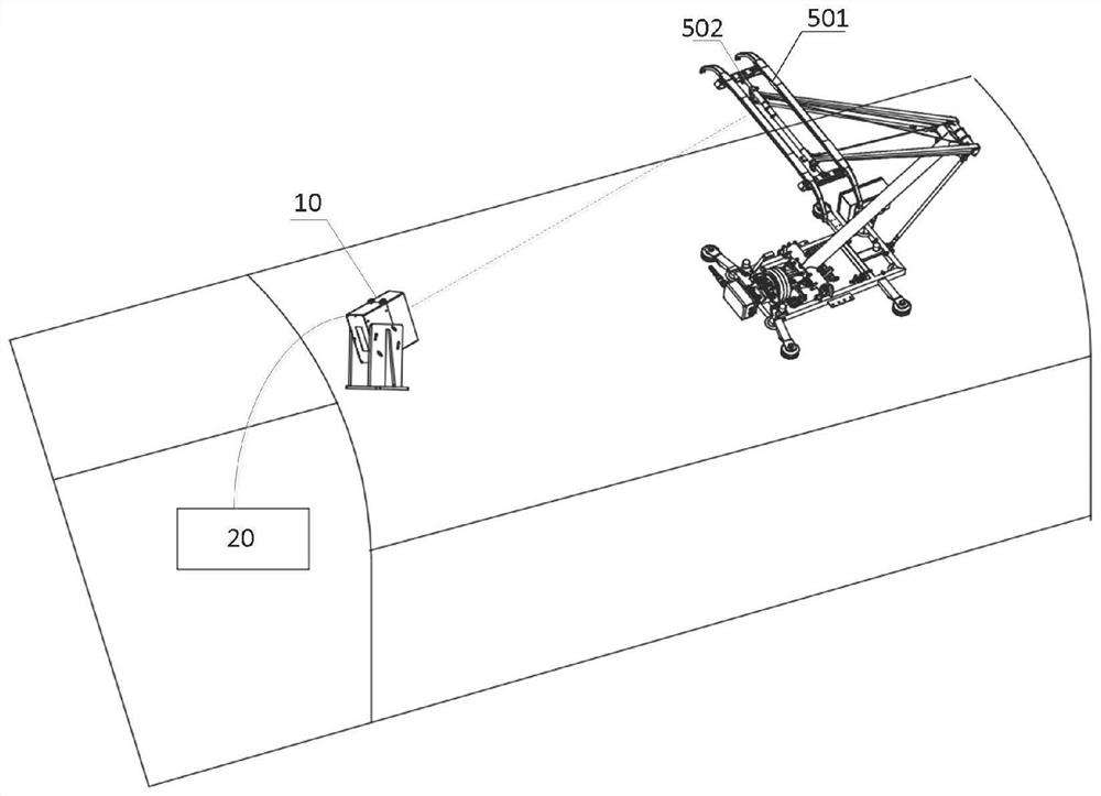
[0054] Embodiment 1 provides a kind of non-contact pantograph-catenary contact force measurement system based on double three-dimensional targets, such as Figure 1-7 shown, including:

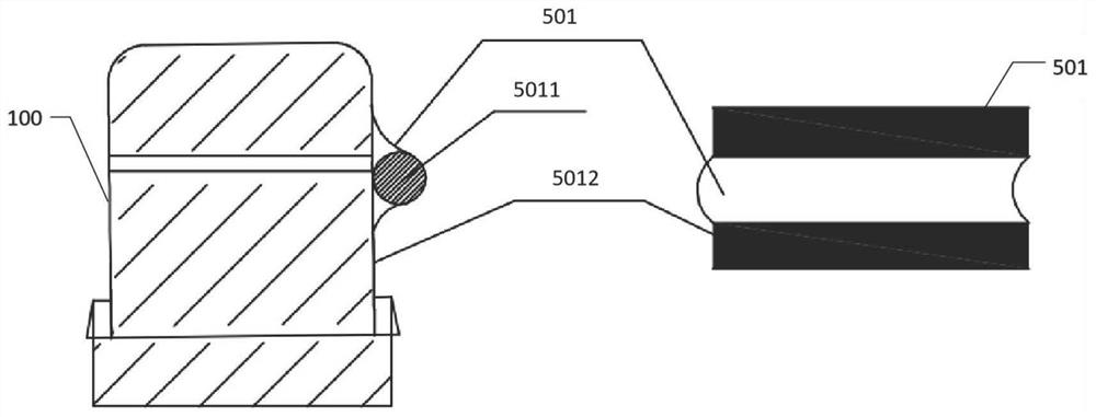
[0055] The first three-dimensional target 501 is arranged on the side of the first carbon slide 100 close to the first support point;

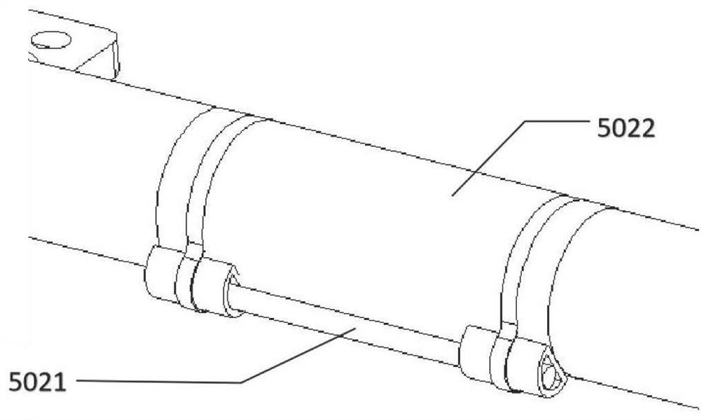
[0056] The second three-dimensional target 502 is arranged on the side of the top tube 200 of the upper arm and corresponds to the position of the first three-dimensional target in the horizontal direction;

[0057] The linear array image acquisition device 10 is vertically arranged on the roof of the train, and is used for shooting target images comprising the first stereoscopic target 501 and the second stereoscopic target 502;

[0058] And the calculation terminal 20 for calculating the pantograph-catenary contact force is realized according to the target image;

[0059] The computing terminal 20 includes:

[0060] A light bar pixel extraction module, co...

Embodiment 2

[0083] This embodiment provides a non-contact pantograph-catenary contact force measurement method based on dual stereo targets, such as Figure 8-10 mentioned, including:

[0084] Step S1, acquire the target image including the first stereo target 501 arranged on the side of the first carbon skateboard 100 and the second stereo target 502 arranged on the side of the top tube 200 of the upper frame taken by the vertical line array camera arranged on the train roof ; The first stereoscopic target 501 and the second stereoscopic target 502 are close to the vertical plane where the longitudinal spring place 401 on one side of the bow head is located; there is no strict requirement for the setting positions of the first stereoscopic target 501 and the second stereoscopic target 502, only restrictions They are located on the same vertical plane, so that the line camera can simultaneously capture the light stripe images corresponding to the first three-dimensional target 501 and the...


PUM


Abstract

The invention relates to the field of rail transit pantograph-catenary relationship detection, in particular to a non-contact pantograph-catenary contact force measurement system based on double three-dimensional targets. The system comprises a first three-dimensional target which is arranged on the side surface, close to the first supporting point, of the first carbon contact strip; a second three-dimensional target which is arranged on the side surface of the upper arm rod jacking pipe and corresponds to the position of the first three-dimensional target in the horizontal direction; linear array image acquisition equipment which is vertically arranged on a train ceiling and is used for shooting a target image containing the first three-dimensional target and the second three-dimensionaltarget; and a calculation terminal which is used for computing bow net contact force according to the target image; the calculation terminal comprises a light bar pixel extraction module, a first elastic force calculation module, a second elastic force calculation module and a bow net contact force output module. Compared with traditional contact pressure sum calculation and non-contact pressure sum calculation of multiple sets of targets, the system has the advantage that the equipment cost is remarkably reduced.

Description

technical field [0001] The invention relates to the field of pantograph-catenary relationship detection in rail transit, in particular to a non-contact pantograph-catenary contact force measurement system based on dual three-dimensional targets. Background technique [0002] The electric locomotive obtains electric energy through the sliding contact between the pantograph slide plate and the catenary wire. When the moving pantograph passes through the relatively static catenary, the catenary is disturbed by external force, so the contact between the pantograph and the catenary There is a dynamic interaction between the two systems, and the pantograph-catenary system produces a specific form of vibration. When the vibration is severe, it can cause the pantograph slide plate to be out of contact with the contact wire, forming an off-line, generating arcs and sparks, accelerating the insulation damage of electrical appliances, causing electromagnetic interference to communicati...

Claims


Application Information

Patent Timeline
Patent Type & Authority Applications(China)
IPC IPC(8): G01L1/24
CPCG01L1/24
Inventor 李想王瑞锋张金鑫黄成亮占栋金友涛陈洪友李一
Owner CHENGDU TANGYUAN ELECTRICAL APPLIANCE
Why Eureka
Try Eureka