Mobile phone antenna with inductive coupling monopole branch and capacitive coupling ring branch

A technology of capacitive coupling and inductive coupling, which is applied in the direction of circuits, antennas, antenna grounding devices, etc., can solve the problems of small, light and thin mobile phones, and occupy a large volume, and achieve simple and easy-to-understand structure, easy processing and manufacturing, and structure Design novel effects

Active Publication Date: 2017-02-15
SYSU CMU SHUNDE INT JOINT RES INST +1
View PDF4 Cites 10 Cited by
  • Summary
  • Abstract
  • Description
  • Claims
  • Application Information

AI Technical Summary

Problems solved by technology

[0003] The traditional PIFA antenna in the 2G era is mostly three-dimensional, with a relatively thick section and a relatively large footprint, which cannot meet the needs of small and light mobile phones.

Method used


Image

  • Mobile phone antenna with inductive coupling monopole branch and capacitive coupling ring branch
  • Mobile phone antenna with inductive coupling monopole branch and capacitive coupling ring branch
  • Mobile phone antenna with inductive coupling monopole branch and capacitive coupling ring branch

Examples


Embodiment Construction

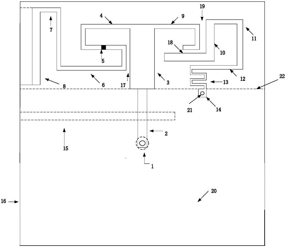
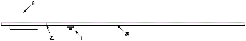
[0042] The present invention will be further described in detail below in conjunction with the accompanying drawings and specific embodiments.

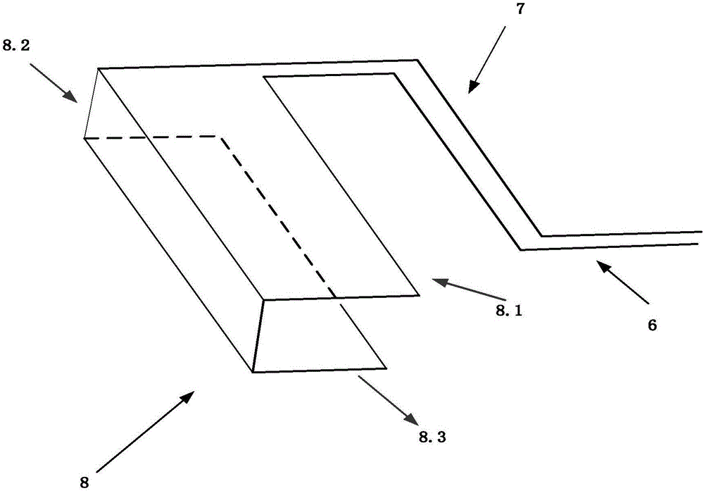
[0043] In the figure: 1-feed connector, 2-microstrip feeder, 3-radiating trunk, 4-the first L-shaped branch in the inductive coupling monopole branch, 5-chip inductor, 6-inductive coupling unit The second L-shaped branch in the pole branch, the third L-shaped branch in the 7-inductively coupled monopole branch, the folded microstrip in the 8-inductively coupled monopole branch, the 8.1-folded microstrip Strip upper surface, 8.2-folded microstrip side, 8.3-folded microstrip lower surface, 9-first L-shaped stub in capacitive coupling loop branch, 10-second L in capacitive coupling loop branch branch, the third L-shaped branch in the 11-capacitive coupling ring branch, the fourth L-shaped branch in the 12-capacitive coupling ring branch, the curved branch in the 13-capacitive coupling ring branch, 14-square microstrip, 15-floor slot, 16...


PUM


Abstract

The invention discloses a mobile phone antenna with an inductive coupling monopole branch and a capacitive coupling ring branch. The mobile phone antenna with the inductive coupling monopole branch and the capacitive coupling ring branch comprises a medium plate, a feeder joint, a micro-strip feeder line, a main radiation circuit, an inductive coupling monopole branch, a capacitive coupling ring branch, a short-circuit nail and a floor plate; the floor plate is located on the lower surface of the medium plate, and a floor plate groove is formed in the floor plate; the micro-strip feeder line, the main radiation circuit, the inductive coupling monopole branch and the capacitive coupling ring branch are located on the upper surface of the medium plate; the micro-strip feeder line is printed on the middle line of the medium plate; the main radiation circuit is printed on the middle line of the medium plate, is connected with the micro-strip feeder line and is overlapped with the middle line of the micro-strip feeder line; the central feed needle of the feeder joint penetrates the medium plate to be connected with the micro-strip feeder line; and the outer conductor of the feeder joint is connected with the surface of the floor plate. The antenna is composed of the inductive coupling monopole branch and the capacitive coupling ring branch; and by combining with the advantages of the two structures, including, the monopole and the ring, the mobile phone antenna realizes advantages of the antenna such as multiple frequencies, broad band and easy processing under the condition of a relatively small size.

Description

technical field [0001] The present invention relates to the radio field, and more specifically relates to a mobile phone antenna with an inductively coupled monopole branch plus a capacitively coupled loop branch, and the mobile phone antenna covers 2G, 3G and 4G frequency bands. Background technique [0002] Although the history of mobile communication is not long, its development is very rapid. From the beginning of the "big brother" external mobile phone antenna - helical external antenna, using analog signals to barely maintain the communication effect; later, the emergence of built-in PIFA antennas and digital signals The large-scale application of mobile communication has begun to enter the 2G era of stable communication, but with the changes of the times, people have more and more requirements for mobile phones. Only satisfying the basic communication functions can not meet people's needs, so the third generation of mobile multi-functional mobile phones and the fourth...

Claims


Application Information

Patent Timeline
Patent Type & Authority Applications(China)
IPC IPC(8): H01Q1/38H01Q1/48H01Q1/50H01Q5/10H01Q5/28
CPCH01Q1/38H01Q1/48H01Q1/50H01Q5/10H01Q5/28
Inventor 徐畅刘菊华李元新龙云亮
Owner SYSU CMU SHUNDE INT JOINT RES INST
Why Eureka
Try Eureka