Low carbon charger

A charger and charging unit technology, applied in the electronic field, can solve the problems of increasing the overall scrapping of chargers, fragile charging tubes, damage, etc.

Inactive Publication Date: 2017-03-15
CHONGQING NINGLAI SCI & TRADE
View PDF4 Cites 0 Cited by
  • Summary
  • Abstract
  • Description
  • Claims
  • Application Information

AI Technical Summary

Problems solved by technology

[0008] The reason for the lack of current products is that there is no constant current and pulse charging circuit, and this circuit has a relatively simple circuit, and can flexibly adjust the relationship between charging and stopping, and the second is that it does not have a limited voltage. A circuit that combines the end of charging (this method is suitable for activated batter

Method used


Image

  • Low carbon charger
  • Low carbon charger
  • Low carbon charger

Examples


Embodiment Construction

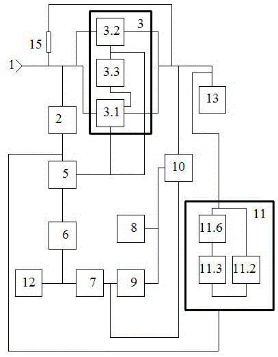
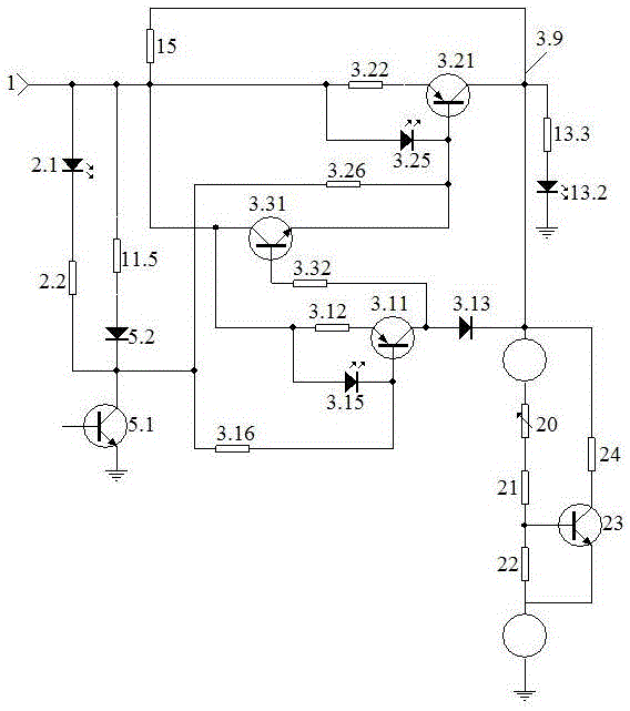
[0115] figure 1 figure 2 An example of a low-carbon charger implementation is given, image 3 and Figure 4 Example of detection map in implementation.

[0116] 1. Select components: The inverters in this method are all welded by Schmidt circuit, and the discharge resistor is a high-power resistor.

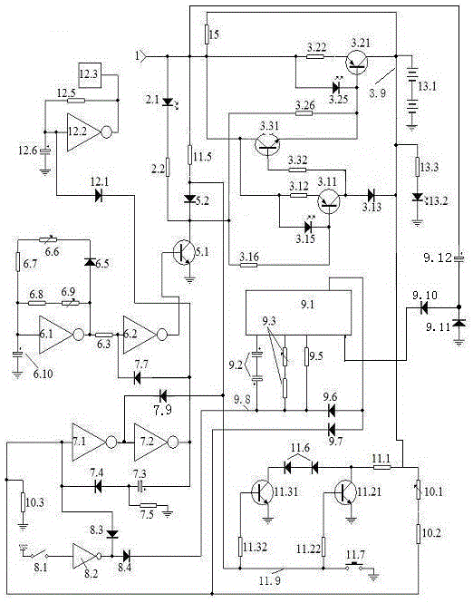
[0117] 2. Make the circuit control board, welding components: connect figure 2 Make the circuit control board according to the schematic diagram, connect figure 2 Schematic of soldered components.

[0118] 3. Power on, check and debug.

[0119] Check that the welding is correct, and then conduct power-on inspection and debugging.

[0120] 1. Check the constant current source part.

[0121] Such as image 3 Weld a dummy load as shown, connect a triode to form an adjustable voltage regulator analog circuit, and replace the charged battery as a dummy load. Use the ammeter of the multimeter to string the red pen in the dummy load, or connect the red pen to the anode of the ...


PUM


Abstract

The invention relates to a low carbon charger which belongs to electronic technology field. The charger comprises a process indicating unit, a power charging unit, an interface unit, a pulse unit, a completion unit, a selection unit, a counting unit, a voltage limiting and starting unit, a power discharging unit, a voice control unit, a load unit and a trickle resistor. The welding of the power charging unit is put together with the power discharging unit in order for a constant current form and is subject to the control of the pulse unit; therefore, the time in which power charging and power discharging both occur is longer than pulse constant current charging form of the power discharging time. The voltage limiting and starting unit and the counting unit trigger the completion unit respectively to develop two completion forms for the selection unit to choose from in a flexible and convenient manner. Both the power charging unit and the power discharging unit are provided with a working tube and a standby tube. When the working tube is damaged, the standby tube replaces it for functioning. In this way, the service lifetime of the charger can be ensured. When the power charging is completed, the power charging unit and the power discharging unit are closed; the trickle resistor provides the charged battery trickle current necessary for its maintenance. The units of the invention are well connected, comply with science rules and achieve high reliability in comprehensive use.

Description

technical field [0001] It belongs to the technical field of electronic technology. Background technique [0002] With the enrichment of modern life, there are more and more types of electrical appliances using batteries, such as digital machines, mobile phones, etc., and many types of chargers have appeared for this reason, but there are still many types of low-carbon and environmentally friendly charging circuits in these types. exist. [0003] One of its meanings is that in current products, the charging director, which is the circuit transistor that connects and shuts off the charging, is easily damaged. Once damaged, the charger becomes garbage. According to statistics, this failure has become the main failure point of the charger. It is a great waste to turn it into garbage just because of this damage. cost, so people are often throwing away). [0004] The second meaning is that during the charging process, the battery is not charged scientifically, which affects the...

Claims


Application Information

Patent Timeline
IPC IPC(8): H02J7/00
Inventor 宁永敭宁永健
Owner CHONGQING NINGLAI SCI & TRADE
Why Eureka
Try Eureka