Supporting roller set mechanism with line deflection preventing function

A technology for idler groups and anti-deviation, which is applied in the direction of rollers, conveyors, and conveyor objects. It can solve the problems of difficult disassembly and replacement, failure to meet the needs of working conditions, and complex structure of the deviation correction mechanism. It is easy to use, The effect of simple structure

Inactive Publication Date: 2017-05-31
安徽清水岩生态科技有限公司
View PDF7 Cites 0 Cited by
  • Summary
  • Abstract
  • Description
  • Claims
  • Application Information

AI Technical Summary

Problems solved by technology

[0002] In recent years, conveyor manufacturers have designed idler roller sets with different adjustment structures. For example, the existing friction-centered idler set is composed of two friction rollers, a middle roller, and upper and lower beams. The friction roller and the middle roller are located at The upper part of the top beam and the middle part between the upper and lower beams are self-balancing and centering mechanisms, which have a certain effect of offset adjustment, but this structure can only meet the conditions of a good working environment, and cannot meet the needs of different working conditions
[0003] In addition, the structure of the existing correction mechanism is slightly complicated, and it is not easy to disassemble, replace and install. Here is a solution

Method used


Image

  • Supporting roller set mechanism with line deflection preventing function
  • Supporting roller set mechanism with line deflection preventing function
  • Supporting roller set mechanism with line deflection preventing function

Examples


Embodiment Construction

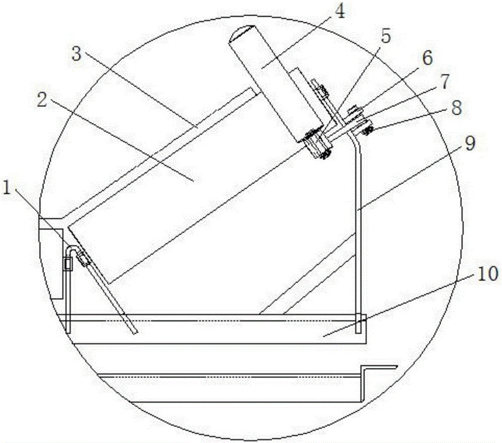
[0012] An idler group mechanism with anti-deviation function, such as figure 1 As shown, the idler roller set includes a roller bracket 9 and a bracket 1 for installing the roller 2, the roller bracket 9 and the bracket 1 are installed on the top beam 10, the roller 2 carries the conveyor belt 3, and the conveyor belt 3 is equipped with deviation correction parts on both sides , used to prevent and correct the deviation of the conveyor belt 3;

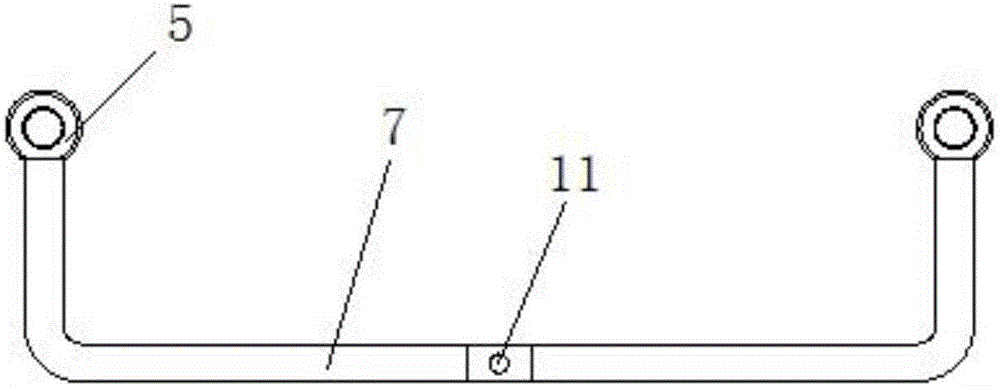
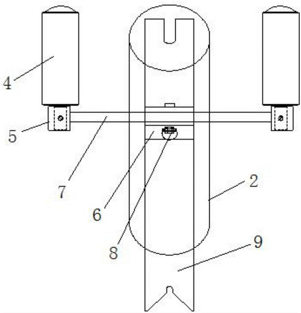
[0013] The deviation correction part includes deviation correction roller 4, steel sleeve 5, side plate 6, rotating shaft 7 and pin shaft 8; see figure 2 , the two ends of the rotating shaft 7 are bent 90 degrees to the same side to form a U-shaped rod body. A steel sleeve 5 is respectively provided at both ends of the bent rotating shaft 7, and a through hole 11 is provided in the middle;

[0014] The two opposite side plates 6 are vertically welded on the outside of the bent end of the roller bracket 9, and the two side plates are ...


PUM


Abstract

The invention discloses a supporting roller set mechanism with a line deflection preventing function. The supporting roller set mechanism comprises rectifying rollers, steel sleeves, side edge plates, a rotating shaft and a pin shaft. The two ends of the rotating shaft are bended by 90 degrees toward the same side to form a U-shaped rod body. The steel sleeves are arranged at the two ends of the bended rotating shaft correspondingly, and a through hole is formed in the middle of the bended rotating shaft. Corresponding pin shaft holes are formed on the two opposite side edge plates, and the rotating shaft is clamped between the two side edge plates. The through hole is aligned to the pin shaft holes, and then, the rotating shaft is fixed between the two side edge plates through the pin shaft. The two bended parts of the rotating shaft stretch into the inner side of a supporting roller set and are located on the two sides of the roller, and the axes of the bended parts of the rotating shaft are parallel to the axes of the rollers. Roller shafts of the two rectifying rollers are mounted in the steel sleeves of the two ends of the rotating shaft correspondingly, and the axes of the rectifying rollers are perpendicular to the axes of the rollers. The structure is simple, manufacturing, mounting and using are all quite convenient, dual rectifying can be achieved without the need of manual adjusting, and safety and reliability are achieved.

Description

technical field [0001] The invention belongs to the technical field of conveying machinery, and relates to a set of idlers, in particular to an idler set mechanism with the function of preventing deviation. Background technique [0002] In recent years, conveyor manufacturers have designed idler roller sets with different adjustment structures. For example, the existing friction-centered idler set is composed of two friction rollers, a middle roller, and upper and lower beams. The friction roller and the middle roller are located at The upper part of the top beam and the middle part between the upper and lower beams are self-balancing centering mechanisms, which have a certain effect of adjusting the deviation, but this structure can only meet the conditions of a good working environment, and cannot meet the needs of different working conditions. [0003] In addition, the structure of the existing correction mechanism is slightly complicated, and it is not easy to disassembl...

Claims


Application Information

Patent Timeline
Patent Type & Authority Applications(China)
IPC IPC(8): B65G39/16B65G15/64
CPCB65G39/16B65G15/64
Inventor 梁俊
Owner 安徽清水岩生态科技有限公司
Why Eureka
Try Eureka