Separator assembly for fuel cell and method of manufacturing the same

a technology of separator assembly and fuel cell, which is applied in the direction of sustainable manufacturing/processing, final product manufacturing, electrochemical generators, etc., can solve the problems of low strength of metal separator, increase in error rate, and deterioration of stack alignment, so as to improve the performance of cells, reduce the deviation between cell performance, and improve the structural stability of fuel cell stacks

Active Publication Date: 2017-08-24
HYUNDAI MOTOR CO LTD +1
View PDF3 Cites 0 Cited by
  • Summary
  • Abstract
  • Description
  • Claims
  • Application Information

AI Technical Summary

Benefits of technology

[0011]The present invention provides a separator assembly for a fuel cell that improves the structural stability and durability of a fuel cell stack by structurally improving the strengths of an anode separator and / or a cathode separator, and mass-production of a stack can be insured, and a method of manufacturing the same.
[0016]According to the separator assembly for a fuel cell of the exemplary embodiment of the present invention, the structural stability of a fuel cell stack can be improved, a performance of cells can be improved, and a deviation between performances of cells can be reduced by improving an alignment of stacks, thus allowing for the mass-production of fuel cell stacks.

Problems solved by technology

As a result, however, these metal separators have low strength and increase in their spring back as the thickness of the material decreases.
This causes deterioration in the alignment of the stacks and an increase in error rates of the metal separators that influence mass-production of the stacks.
In a fuel cell stack in which a plurality of unit cells are stacked, an alignment error between adjacent unit cells and an alignment error between adjacent separators may occur.
As such, it becomes more difficult to uniformly stack a separator, an MEA, and a GDL (gas dispersing layer) due to lack of strength and an increase of a spring back as the separator becomes thinner, and a possibility of generating an alignment error between adjacent separators that influences a structure and a performance of the stack.
However, as the metal separator becomes thinner, the quality of metal separator decreases.
For example, deformation of a separator or generation of a gasket burr due to an injection-molding pressure may occur, and thus an error rate of the metal separators increases.

Method used


Image

  • Separator assembly for fuel cell and method of manufacturing the same
  • Separator assembly for fuel cell and method of manufacturing the same
  • Separator assembly for fuel cell and method of manufacturing the same

Examples


Embodiment Construction

[0026]Hereinafter, exemplary embodiments of the present invention will be described so that those skilled in the art to which the present invention pertains can easily carry out the invention.

[0027]The terminology used herein is for the purpose of describing particular embodiments only and is not intended to be limiting of the invention. As used herein, the singular forms “a”, “an” and “the” are intended to include the plural forms as well, unless the context clearly indicates otherwise. It will be further understood that the terms “comprises” and / or “comprising,” when used in this specification, specify the presence of stated features, integers, steps, operations, elements, and / or components, but do not preclude the presence or addition of one or more other features, integers, steps, operations, elements, components, and / or groups thereof. As used herein, the term “and / or” includes any and all combinations of one or more of the associated listed items.

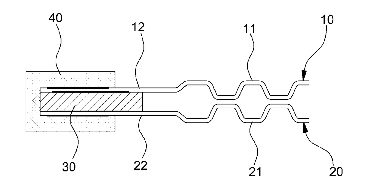
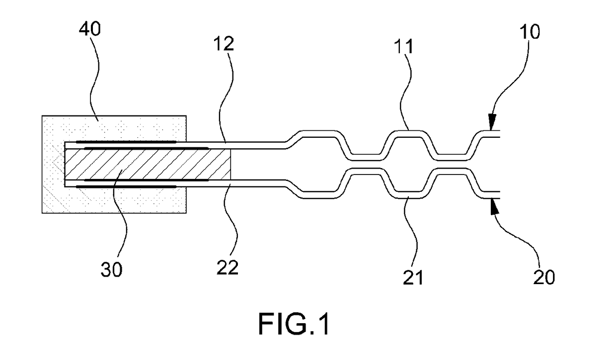
[0028]As shown in FIG. 1, a se...


PUM

PropertyMeasurementUnit
timeaaaaaaaaaa
durabilityaaaaaaaaaa
chemical energyaaaaaaaaaa

Abstract

A separator assembly for a fuel cell having an anode separator, a cathode separator, a cooling surface frame, and a gasket. In particular, the cooling surface frame is integrally bonded between peripheral portions of the anode separator and the cathode separator. Additionally, the gasket encloses the peripheral portions of the anode separator and the cathode separator between which the cooling surface frame is interposed.

Description

CROSS-REFERENCE TO RELATED APPLICATION[0001]This application claims under 35 U.S.C. §119(a) the benefit of Korean Patent Application No. 10-2013-0162012, filed on Dec. 24, 2013, the entire contents of which are incorporated herein by reference.BACKGROUND[0002](a) Technical Field[0003]The present invention relates to a separator assembly to be disposed in a fuel cell that structurally improves structural safety and the durability of a fuel cell stack and allows for mass-production of fuel cell stacks, and a method of manufacturing the same.[0004](b) Background Art[0005]In general, fuel cells generate electric power by directly converting chemical energy generated by oxidation of a fuel into electric energy, and directly supply hydrogen produced by modifying or purifying a hydrocarbon-based fuel or a hydrocarbon-based fuel and air into a fuel cell stack to allow fuel and air to generate an electrochemical reaction and thus generate electrical energy.[0006]In a fuel cell stack, a plura...

Claims


Application Information

Patent Timeline
Patent Type & Authority Applications(United States)
IPC IPC(8): H01M8/0267B29C65/48H01M8/0297B29C45/14H01M8/0273H01M8/0286
CPCH01M8/0267H01M8/0273H01M8/0286H01M8/0297B29L2031/3468B29C45/14336B29C65/48B29L2031/265B29C45/14467H01M8/0206B29C45/14311Y02E60/50Y02P70/50H01M8/02B29C2045/14459B29C2045/14532H01M8/0202
Inventor JIN, SANG MOONYANG, YOO CHANGBAECK, SUK MIN
Owner HYUNDAI MOTOR CO LTD
Why Eureka
Try Eureka