Imaging system and imaging method for imaging a region of interest

a technology which is applied in the field of imaging system and imaging method for imaging a region of interest, can solve the problems of reducing image quality and severe artefacts in reconstructed images, and achieve the effect of less disturbance and higher image quality

Active Publication Date: 2013-09-03
KONINK PHILIPS ELECTRONICS NV
View PDF10 Cites 0 Cited by
  • Summary
  • Abstract
  • Description
  • Claims
  • Application Information

AI Technical Summary

Benefits of technology

[0004]It is an object of the present invention to provide an imaging system, an imaging method and a computer program for imaging a region of interest, which generate a reconstructed image of the region of interest, which is less disturbed by artefacts and comprises therefore a higher image quality.
[0011]The invention is based on the idea that an artefact correction method, which is not sufficiently adapted, generates inconsistencies in the data, which can be identified retrospectively by determining a deviation between the first data, which are not influenced by the artefact correction method, and the second data, which are influenced by the artefact correction method, because the second data have been provided by simulating the providing of the first data using a reconstructed image of the region of interest, wherein the reconstructed image of the region of interest has been reconstructed by using the artefact correction method. This inconsistency between the first data and the second data is a measure for the degree of artefacts within the reconstructed image and, thus, of the image quality. If this inconsistency is reduced, also the disturbing appearance of the artefacts in the reconstructed image is reduced and, therefore, the image quality is increased. Thus, by adapting the artefact correction method such that the deviation between the first and second data is reduced, the image, which is reconstructed by using this adapted artefact correction method, shows an improved image quality.
[0013]It is further preferred that the reconstruction unit is adapted for using an adaptable high density elements correction method as artefact correction method. Preferentially the adaptation unit is adapted for adapting at least one of the following parameters of the high density element correction method: extension of high density elements, absorption of high density elements. This allows reducing artefacts caused by high density elements like metal elements in the reconstructed image and, thus, improving the image quality, if artefacts are caused by high density elements.
[0014]It is further preferred that the reconstruction unit is adapted for using an adaptable beam hardening correction method as artefact correction method. This allows reducing artefacts in the reconstructed image caused by beam hardening.

Problems solved by technology

In computed tomography systems, which use an X-ray source emitting X-rays and a detection unit for detecting the X-rays after having traversed the region of interest, metallic elements, for example, metal implants like hip replacements or dental fillings, cause severe artefacts in the reconstructed images.
But even by using this artefact correction method, strong arte-facts are still present in the reconstructed image, resulting in a decreased image quality.

Method used


Image

  • Imaging system and imaging method for imaging a region of interest
  • Imaging system and imaging method for imaging a region of interest
  • Imaging system and imaging method for imaging a region of interest

Examples


Embodiment Construction

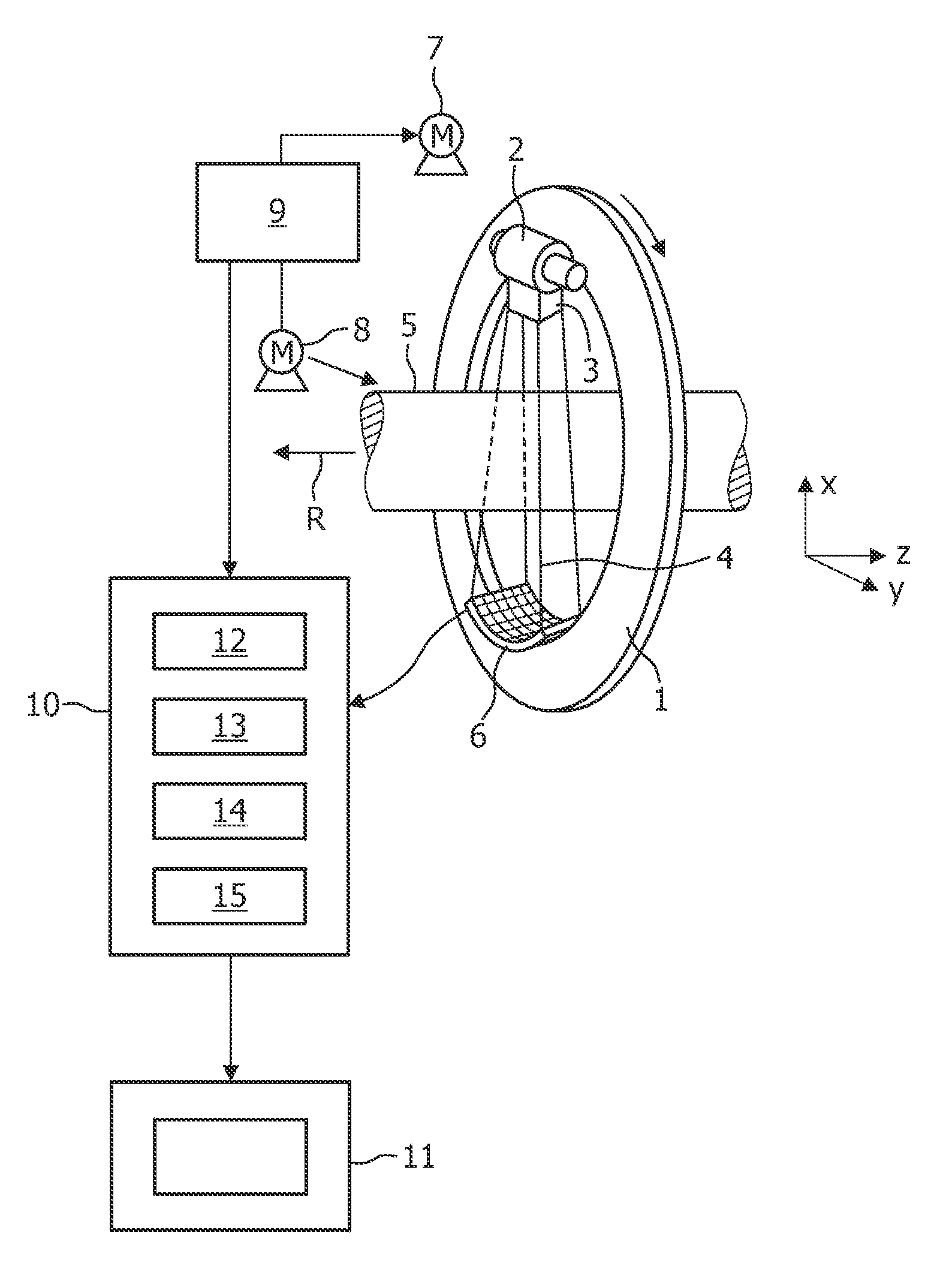
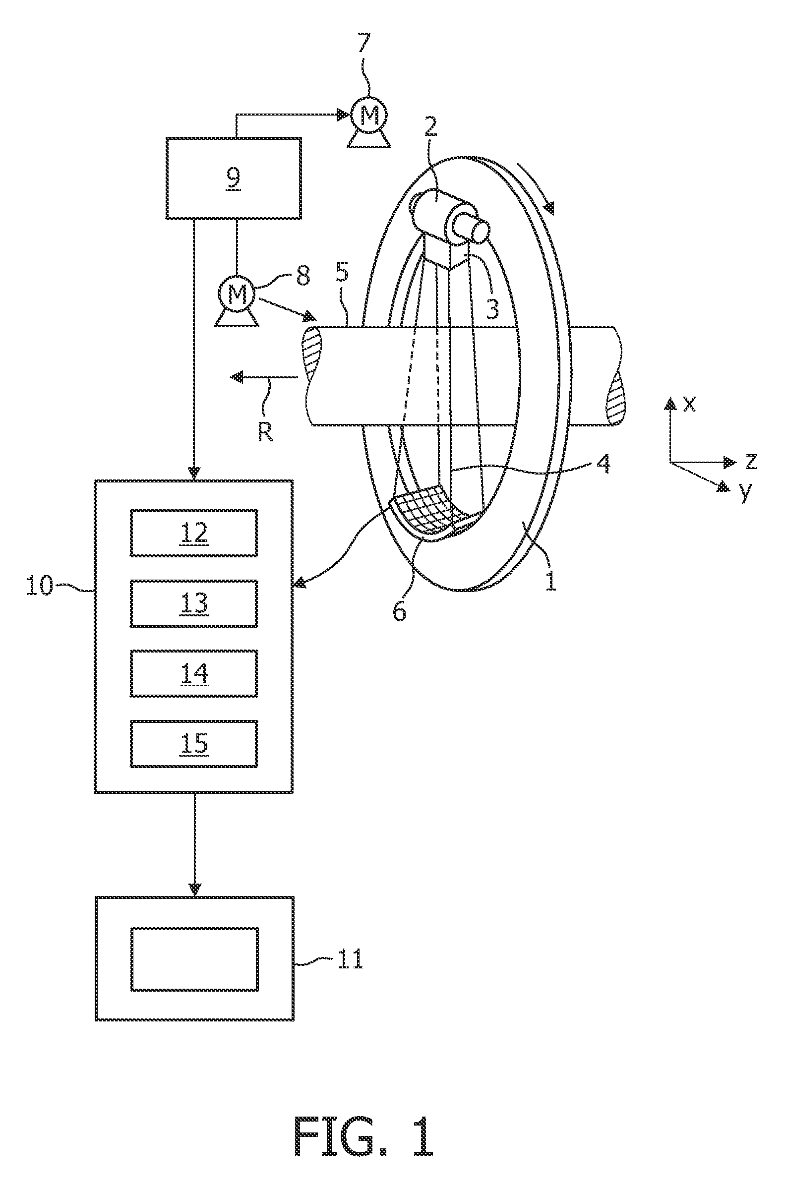
[0028]FIG. 1 shows schematically and exemplarily an imaging system for imaging a region of interest, being, in this embodiment, a computed tomography system. The computed tomography system includes a gantry, which is capable of rotating around an axis of rotation R which extends parallel to the z axis. A radiation source 2, for example, an X-ray tube, is mounted on the gantry 1. The radiation source 2 is provided with the collimator device 3 which forms a conical radiation beam 4 from the radiation emitted by the radiation source 2. In other embodiments, the collimator device 3 can be adapted for forming a radiation beam having another shape, for example, having a fan shape.

[0029]The radiation traverses an object (not shown), such as a patient or a technical object, in a region of interest in a cylindrical examination zone 5. After having traversed the region of interest, the radiation beam 4 is incident on a detection device 6 having, in this embodiment, a two-dimensional detection...


PUM


Abstract

The invention relates to an imaging system for imaging a region of interest, in particular to a computed tomography system. First data for generating an image of the region of interest are provided, which are used by a reconstruction unit (12) for reconstructing an image of the region of interest using an adaptable artefact correction method. Second data are provided by simulating the providing of the first data using the reconstructed image of the region of interest by a second data providing unit (13). A deviation determination unit (14) determines a deviation between the first and second data. An adaptation unit (15) adapts the artefact correction method such that the deviation between the first and second data is reduced and the reconstruction unit (12) reconstructs an image of the region of interest from first the data using the adapted artefact correction method.

Description

FIELD OF THE INVENTION[0001]The invention relates to an imaging system and imaging method for imaging a region of interest. The invention relates further to a corresponding computer program for imaging a region of interest.BACKGROUND OF THE INVENTION[0002]A lot of imaging systems for imaging a region of interest are known, for example, computed tomography systems, magnetic resonance imaging systems, ultrasound imaging systems or nuclear imaging systems. Images generated by these imaging systems generally comprise artefacts, which can be caused by different effects, for example, by movements within a region of interest, which has to be imaged, or by high density elements like metallic elements, which influence radiation traversing the region of interest.[0003]In computed tomography systems, which use an X-ray source emitting X-rays and a detection unit for detecting the X-rays after having traversed the region of interest, metallic elements, for example, metal implants like hip repla...

Claims


Application Information

Patent Timeline
Patent Type & Authority Patents(United States)
IPC IPC(8): G06K9/40
CPCG06T11/006G06T2211/424
Inventor KOEHLER, THOMASFORTHMANN, PETER
Owner KONINK PHILIPS ELECTRONICS NV
Why Eureka
Try Eureka