A cylindrical winding processing equipment for distribution network substation transformers

A technology for processing equipment and substations, applied in the manufacture of inductors/transformers/magnets, circuits, electrical components, etc., it can solve the problems of complex operation, inability to adjust the tensioning position, and low quality of transformers, and achieve the effect of good performance

Active Publication Date: 2018-05-08
HUNAN XIANGBIAN ELECTRIC LIMITED LIABILITY
View PDF4 Cites 0 Cited by
  • Summary
  • Abstract
  • Description
  • Claims
  • Application Information

AI Technical Summary

Problems solved by technology

[0003] In order to solve the above problems, the present invention provides a cylindrical winding processing equipment for distribution network substation transformers, which can solve the existing manual winding process of cylindrical windings and transformers prepared by manually winding cylindrical windings There are problems such as the need to adjust the tension force, the tension position cannot be adjusted with the winding position, complex operation, poor tension effect, inconsistent transformer performance, low transformer qualification rate and low transformer quality, etc., and the cylindrical winding can be realized. Fully automatic tension winding function, can also prepare high-performance transformers with cylindrical windings, without manual operation, with automatic tension adjustment, tension position can be automatically adjusted in real time with the winding position, easy operation, good tension effect Good, uniform transformer performance, high transformer pass rate and good quality of transformers, etc.

Method used


Image

  • A cylindrical winding processing equipment for distribution network substation transformers
  • A cylindrical winding processing equipment for distribution network substation transformers
  • A cylindrical winding processing equipment for distribution network substation transformers

Examples


Embodiment Construction

[0027] In order to make the technical means, creative features, goals and effects achieved by the present invention easy to understand, the present invention will be further described below in conjunction with specific illustrations.

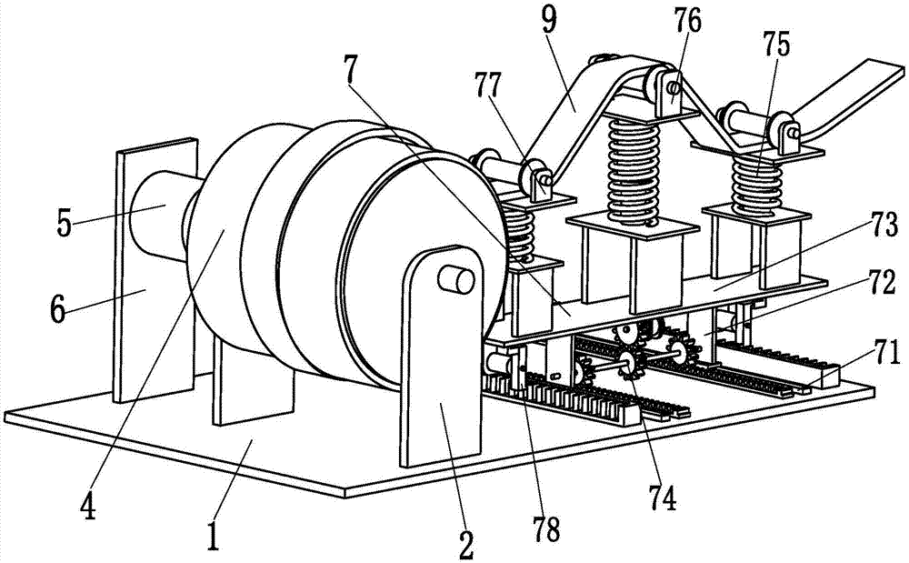
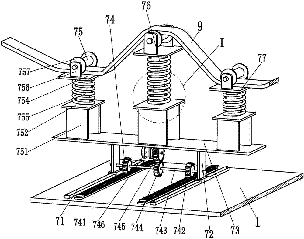
[0028] like Figure 1 to Figure 5 As shown, the embodiment of the present invention provides a cylindrical winding processing equipment, including a bottom plate 1, two mounting ears 2 are symmetrically installed on the upper end surface of the bottom plate 1, and insulating The front end of the cylinder 4 and the insulation cylinder 4 is equipped with a winding motor 5 through a coupling. Drive the insulating cylinder 4 to rotate on the two mounting ears 2, the left end of the bottom plate 1 is equipped with a mobile tensioning device 7, the mobile tensioning device 7 has a V-shaped structure and is wound with a wire bar 9, and the mobile tensioning device 7 can be according to The winding position of the conductor bar 9 is adjusted in real ti...


PUM


Abstract

The invention relates to a bobbin winding processing device and a transformer comprising a bobbin winding. The bobbin winding processing device comprises a bottom plate, wherein two mounting lugs are symmetrically installed on the upper end face of the bottom plate, an insulating cylinder is installed between the two mounting lugs through a bearing, a winding motor is installed at the front end of the insulating cylinder through a coupler, the bottom of the winding motor is installed on a vertical plate through a motor base, the vertical plate is welded on the bottom plate, the insulating cylinder is driven by the winding motor to rotate on the two mounting lugs, a mobile tensioning device is installed at the left end of the bottom plate, a guide line strip is wound around the mobile tensioning device in V-shaped structure, the mobile tensioning device can adjust the position in real time according to the winding position of the guide line strip, and does not need manual adjustment on tensioning positions, the initial end of the guide line strip is wound around the insulating cylinder, and a bobbin winding is formed by winding the guide line strip on the outer wall of the insulating cylinder more than once. The bobbin winding processing device not only can achieve a full-automatic tensioning winding function of the bobbin winding, but also can be prepared into the high performance transformer comprising the bobbin winding.

Description

technical field [0001] The invention relates to the technical field of transformer processing, in particular to a cylindrical winding processing equipment used for a transformer of a distribution network substation. Background technique [0002] The transformer uses the principle of electromagnetic induction to change the AC voltage device. It is composed of a coil and a magnetic core. It has functions such as voltage conversion, current conversion, impedance conversion, isolation, and voltage stabilization. Therefore, it is widely used in distribution network substations. The coil It is the main structure that affects the performance of the transformer. In the production process of the transformer coil, to ensure that the outer diameter and axial height of the coil to be wound meet the design requirements, the winding wire must be tightened during the winding process to improve the winding. The degree of tightness of the winding ensures that the winding is not damaged or th...

Claims


Application Information

Patent Timeline
Patent Type & Authority Patents(China)
IPC IPC(8): H01F41/064H01F41/071H01F41/094H01F41/082
CPCH01F41/064H01F41/071H01F41/082H01F41/094
Inventor 储德姣
Owner HUNAN XIANGBIAN ELECTRIC LIMITED LIABILITY
Why Eureka
Try Eureka