Camshaft adjusting device

Active Publication Date: 2015-12-16
SCHAEFFLER TECH AG & CO KG
View PDF6 Cites 0 Cited by
  • Summary
  • Abstract
  • Description
  • Claims
  • Application Information

AI Technical Summary

Problems solved by technology

Axial bearings are not identified, but must be mandatory

Method used


Image

  • Camshaft adjusting device
  • Camshaft adjusting device

Examples


Embodiment Construction

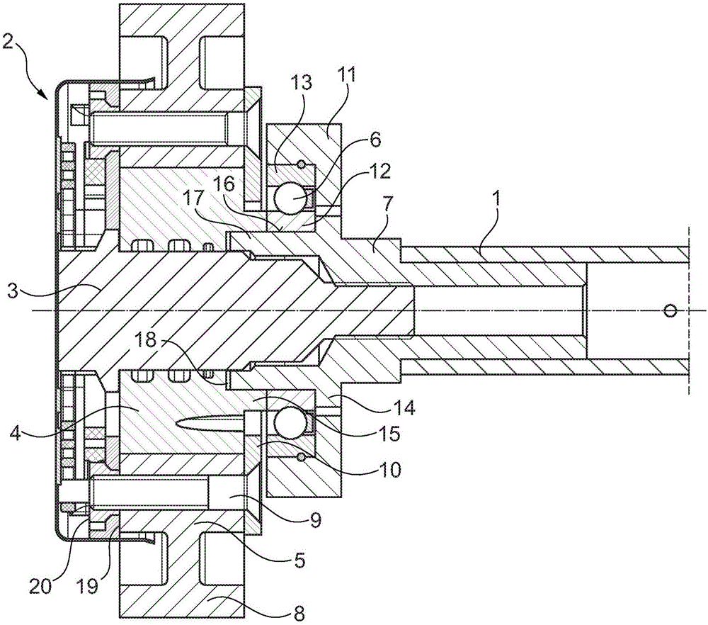
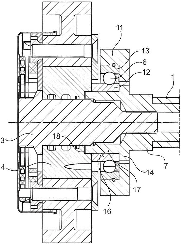
[0017] exist figure 1 A camshaft adjusting device according to the invention of an internal combustion engine with a camshaft 1 and a camshaft adjuster 2 is shown in FIG. The camshaft adjuster 2 includes a stator 5 drivable by the crankshaft and a rotor 4 rotatably connected to the camshaft 1 . On the stator 5 is provided a drive wheel 8 which is wound by a continuous traction mechanism to transmit the rotational movement of the crankshaft. Instead of the drive wheel 8 a toothing can also be provided, depending on whether a chain, a toothed belt or a toothless belt is provided as the continuous traction mechanism for the transmission of the rotational movement. The stator 5 also has a plurality of stator webs with through-bores arranged therein, which divide the annular space present between the stator 5 and the rotor 4 into a plurality of pressure chambers. The rotor 4 has a plurality of vanes which extend radially outwards to the inner wall 5 of the stator and divide the p...


PUM


Abstract

The invention relates to a camshaft adjusting device, comprising a camshaft (1) and a camshaft adjuster (2) having a stator (5) that can be connected to a crankshaft of an internal combustion engine and a rotor (4) that is rotatably mounted in the stator (5) and can be connected to the camshaft (1) and a clamping device (3) for clamping the rotor (4) to the camshaft and a rolling bearing (8) absorbing both axial and radial forces for mounting the camshaft adjusting device in a stationary housing (11), wherein the rotor (4) is clamped to the camshaft (1) by means of the clamping device (3) via an inner ring (12) or an outer ring (13) of the rolling bearing (6).

Description

technical field [0001] The invention relates to a camshaft adjusting device having the features according to the preamble of claim 1 . Background technique [0002] Such a camshaft adjusting device is known, for example, from document EP1979582B1. The camshaft adjusting device comprises a camshaft and a camshaft adjuster, which in its basic structure has a stator drivable by the crankshaft and a rotor connected to the camshaft in a rotationally fixed manner. An annular chamber is arranged between the stator and the rotor, and the annular chamber is divided into a plurality of pressure chambers through radially outwardly protruding protrusions that are connected to the stator in a rotationally fixed manner. The outwardly protruding blades divide into two working chambers with opposite directions of action. Depending on the pressure medium that acts on the working chamber, the rotor is then adjusted in the "advance" or "retard" direction relative to the stator and thus the c...

Claims


Application Information

Patent Timeline
Patent Type & Authority Applications(China)
IPC IPC(8): F01L1/344F01L1/047
CPCF01L1/3442F01L2001/0476F16C35/063F16C35/077F16C19/16F16C2360/18F01L1/047F01L1/344
Inventor 鲍里斯·普茨阿里·巴伊拉克达尔
Owner SCHAEFFLER TECH AG & CO KG
Why Eureka
Try Eureka