A graphical management method and system for optical fiber termination

A management method and management system technology, applied in the optical fiber termination graphical management method and system field, can solve problems such as outdated optical fiber termination configuration and supervision methods, inability of the system to automatically diagnose, and difficulty in troubleshooting communication line faults, etc., to achieve simplified optical fiber End-to-end management, high application significance, and the effect of improving management and monitoring efficiency

Active Publication Date: 2020-08-25
LIUZHOU DADI TELECOMM EQUIP +1
View PDF4 Cites 0 Cited by
  • Summary
  • Abstract
  • Description
  • Claims
  • Application Information

AI Technical Summary

Problems solved by technology

[0011] In the traditional optical cable network management system, manual inspection is required to detect the looseness or damage of the fiber core connectors in the optical fiber distribution frame ODF. high
Moreover, in the optical fiber network management system, the number of terminals and fiber cores of an optical cable is very large. How to configure the fiber ends is a big challenge. Simple manual entry can easily miss some terminals and fiber cores, and it is necessary to implement Personnel repeatedly check
In general, the current configuration and supervision methods for optical fiber termination are relatively backward, with low efficiency and high cost

Method used


Image

  • A graphical management method and system for optical fiber termination
  • A graphical management method and system for optical fiber termination
  • A graphical management method and system for optical fiber termination

Examples


Embodiment 1

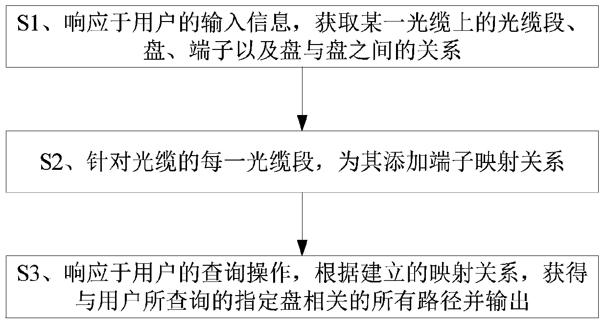
[0121]In the actual implementation of this embodiment, data processing in the background and data interaction with the user in the software foreground are divided. The user inputs the basic data into the background storage, and the background analyzes the cable segment, disk, the relationship between disks, terminals and other information on a certain optical cable and then transmits it to the front desk. The terminal operation interface hides the complex business logic and presents an easy-to-use, fool-like graphical user interface to the user.

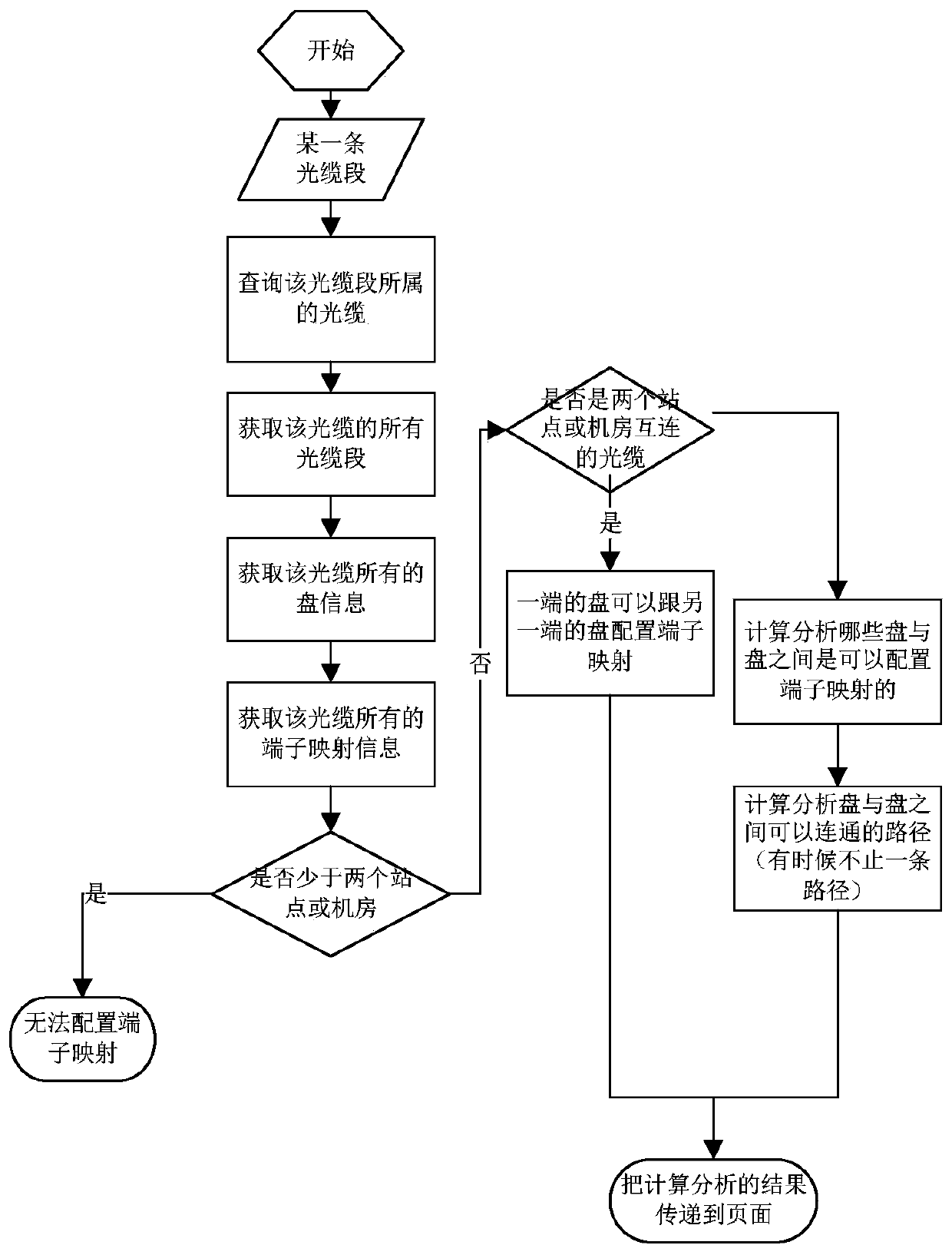
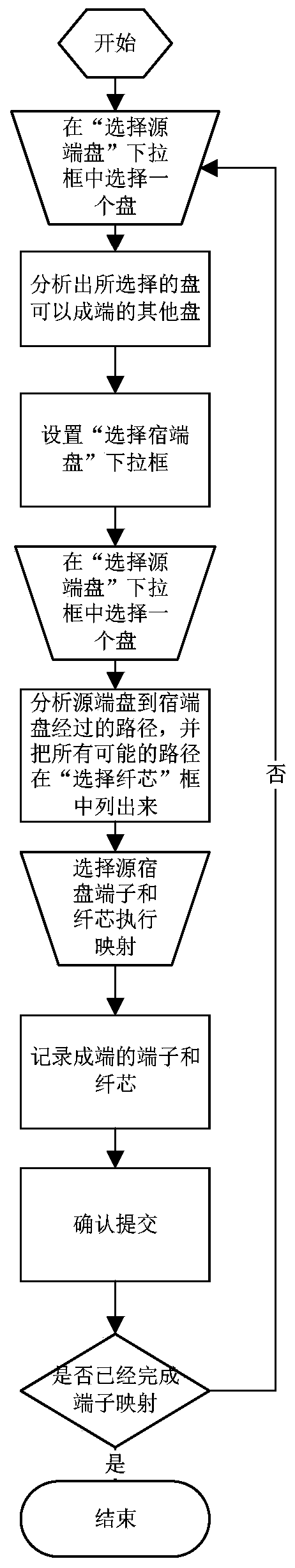
[0122] Specifically, for each cable segment of the cable, the process of adding terminal mapping relationship to it is divided into two processes, such as figure 2 and image 3 as shown, figure 2 The main display is the process of analyzing and obtaining mapping path information, including the following steps:

[0123] 1. A certain optical cable segment: the user selects an optical cable segment on the interface, and the front...


PUM


Abstract

The invention discloses an optical fiber terminating graphical management method and system. The method comprises the steps of: S1, in response to input information of a user, acquiring optical cable sections, discs, terminals and a relation between the discs on a certain optical cable; S2, adding a terminal mapping relation for each optical cable section of the optical cable; and S3, in response to a query operation of the user, acquiring all paths related to the designated disc inquired by the user according to the established mapping relation and outputting the paths. The method and the system can simplify the optical fiber terminating management to a great extent, facilitate operation and management, bring great convenience to implementers, improve the management monitoring efficiency, reduce the cost, and can be widely applied to the optical fiber network management industry.

Description

technical field [0001] The invention relates to the field of optical fiber network management, in particular to a graphical management method and system for optical fiber termination. Background technique [0002] Explanation of terms of the present invention: [0003] Nodes: link nodes in the optical fiber network, including sites, computer rooms, T-connectors, etc.; [0004] Optical cable segment: an optical fiber line linking two nodes, and an optical cable segment generally contains multiple optical fibers; [0005] T connector: it can link multiple optical cable segments, and make the multiple optical cable segments interoperable and interconnected; [0006] Disk: refers to the optical fiber fusion disk; [0007] Terminal: refers to the optical fiber interface on the optical fiber splicing tray; [0008] Mapping: In this application, it specifically refers to the pairing relationship between two terminals and multiple fiber cores; [0009] ODF: Optical Distribution...

Claims


Application Information

Patent Timeline
Patent Type & Authority Patents(China)
IPC IPC(8): H04L12/24H04B10/075
CPCH04B10/075H04L41/06H04L41/22
Inventor 麦俊进甘智全陈刚
Owner LIUZHOU DADI TELECOMM EQUIP
Why Eureka
Try Eureka