Automatic pressure relief valve

A technology that automatically vents and releases the valve body. It is applied in the direction of balance valves, valve devices, and valve details. It can solve the problems of manual adjustment and large valve core force, and achieve the effect of uniform force on the upper and lower sides and prolonging the service life.

Inactive Publication Date: 2017-07-21
YANCHENG OURUN PETROCHEMICAL EQUIP MFG CO LTD
View PDF5 Cites 2 Cited by
  • Summary
  • Abstract
  • Description
  • Claims
  • Application Information

AI Technical Summary

Problems solved by technology

[0003] The traditional pressure relief valve is composed of a valve body and a valve stem. The valve core is installed on the valve stem, and the pressure is released by the valve core. There are the following problems: 1. During use, the pressure can only be adjusted automatically by the device , can not be manually adjusted according to the situation of use; 2. The valve core is connected to the valve stem at one end. During use, the valve core is subjected to a large force and is seriously damaged.

Method used


Image

  • Automatic pressure relief valve
  • Automatic pressure relief valve
  • Automatic pressure relief valve

Examples


Embodiment Construction

[0018] The following will clearly and completely describe the technical solutions in the embodiments of the present invention with reference to the accompanying drawings in the embodiments of the present invention. Obviously, the described embodiments are only some, not all, embodiments of the present invention. Based on the embodiments of the present invention, all other embodiments obtained by persons of ordinary skill in the art without making creative efforts belong to the protection scope of the present invention.

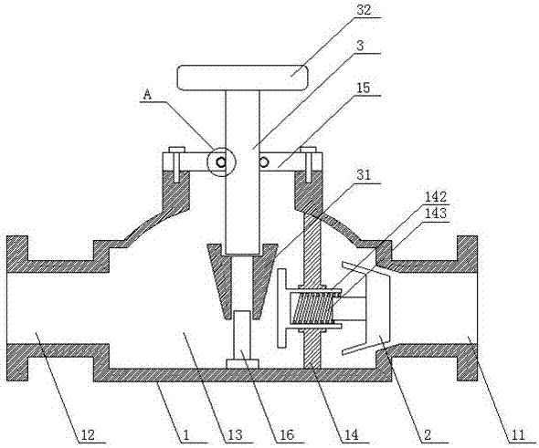
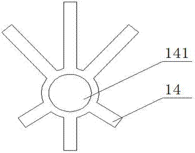
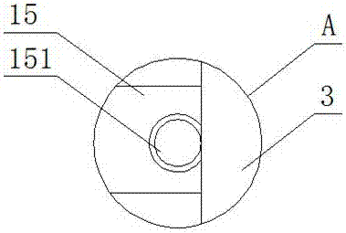
[0019] see Figure 1-3 , the present invention provides a technical solution: an automatic pressure relief valve, including a valve body 1, a valve core 2 and a valve stem 3, a liquid inlet 11 is opened on one side of the valve body 1, and a liquid inlet 11 is opened on the other side of the valve body One side is provided with a liquid outlet 12, the inside of the valve body 1 is provided with a cavity 13, and the two ends of the cavity 13 are respectively co...


PUM


Abstract

The invention discloses an automatic pressure relief valve comprising a valve body, a valve element and a valve rod. A liquid inlet is formed in one side of the valve body; a liquid outlet is formed in the other side of the valve body; a cavity is formed inside the valve body, and the two ends of the cavity are connected with the liquid inlet and the liquid outlet correspondingly; a supporting frame is installed on the side, at the end of the liquid inlet, inside the valve body; a circular through hole is formed in the lower end of the supporting frame, and a T-shaped circular cylinder is installed inside the circular through hole; a compression spring is installed inside the T-shaped circular cylinder; a valve cover is installed at the upper end of the valve body through a bolt; one end of the valve element is installed inside the liquid inlet, and the other end of the valve element is installed inside the T-shaped circular cylinder and connected with one end of the compression spring; a valve rod is installed at the center of the valve cover; a tapered sleeve is installed at the lower end of the valve rod through a thread; and a hand wheel is installed at the upper end of the valve rod. The automatic pressure relief valve has the characteristics of being simple and reasonable in structure and flexible in operation.

Description

technical field [0001] The invention relates to the technical field of pressure pipeline accessories, in particular to an automatic pressure relief valve. Background technique [0002] The pressure relief valve, also known as the safety valve, can automatically open and close according to the working pressure of the system. It is generally installed on the equipment or pipeline of the closed system to protect the safety of the system. When the pressure in the equipment or pipeline exceeds the set pressure of the pressure relief valve, it will automatically open the pressure relief to ensure that the medium pressure in the equipment and pipeline is below the set pressure, protect the equipment and pipeline, and prevent accidents. [0003] The traditional pressure relief valve is composed of a valve body and a valve stem. The valve core is installed on the valve stem, and the pressure is released by the valve core. There are the following problems: 1. During use, the pressure ...

Claims


Application Information

Patent Timeline
Patent Type & Authority Applications(China)
IPC IPC(8): F16K17/04F16K31/60F16K41/02
CPCF16K17/04F16K31/60F16K41/02
Inventor 刘步明
Owner YANCHENG OURUN PETROCHEMICAL EQUIP MFG CO LTD
Why Eureka
Try Eureka