An automatic processing equipment for riser drilling and packaging

A processing equipment and drilling machine technology, applied in metal processing equipment, drilling/drilling equipment, packaging, etc., can solve problems such as slow processing efficiency and inconsistent drilling, and achieve high work efficiency, ensure consistency, and save energy. energy effect

Active Publication Date: 2018-12-14
长兴鼎峰铸材科技股份有限公司
View PDF8 Cites 0 Cited by
  • Summary
  • Abstract
  • Description
  • Claims
  • Application Information

AI Technical Summary

Problems solved by technology

[0003] The existing drilling packaging processing method is that the worker uses a pistol drill to open a hole at the bottom of the riser. After the hole is completed, the wrapping paper is further covered on the riser, and the wrapping paper is tightened with a heat gun. A layer of packaging film is formed on the outside; the processing efficiency is slow, and the drilling is inconsistent, and an automatic equipment that can replace manual work is urgently needed to realize the integrated processing of drilling and packaging

Method used


Image

  • An automatic processing equipment for riser drilling and packaging
  • An automatic processing equipment for riser drilling and packaging
  • An automatic processing equipment for riser drilling and packaging

Examples


Embodiment 1

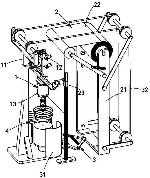
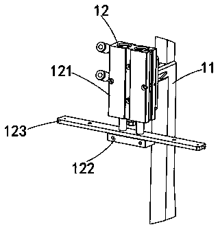
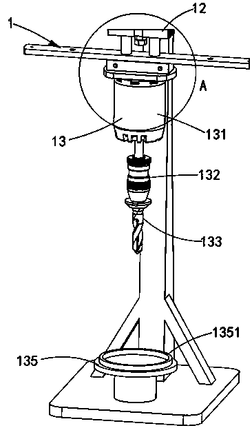
[0073] Such as figure 1 As shown, a riser drilling packaging automation processing equipment includes a drilling mechanism 1 and a sealing mechanism 3, the drilling mechanism 1 is arranged on the front side of the paper feeding mechanism 2, and it includes a drilling frame 11, The lifting assembly 12 and the drilling assembly 13, the lifting assembly 12 is fixedly arranged on the top of the drilling frame 11, and the lower end is connected with the drilling assembly 13;

[0074] The paper feeding mechanism 2 includes a paper feeding frame 21, a paper feeding assembly 22 and a symmetrically arranged paper clamping assembly 23. The paper feeding frame 21 is arranged on the rear side of the drilling frame 11, and the upper end thereof is provided with the The paper feeding assembly 22, the paper clamping assembly 23 is symmetrically arranged on both sides of the paper feeding assembly 22, and it is connected to the lifting assembly 12;

[0075] The sealing mechanism 3 includes a...

Embodiment 2

[0113] Figure 12 It is a structural schematic diagram of Embodiment 2 of a riser drilling packaging automatic processing equipment of the present invention; as Figure 12 As shown, the components that are the same as or corresponding to those in the first embodiment are marked with the corresponding reference numerals in the first embodiment. For the sake of simplicity, only the differences from the first embodiment will be described below. This embodiment two and figure 1 The difference of the shown embodiment one is:

[0114] Such as Figure 12 , Figure 13 and Figure 14 As shown, a riser drilling packaging automation processing equipment, the cutting mechanism 4 is arranged on the lower part of the drilling frame 11, which includes a cutting knife group 41 and a fixed assembly 42, the cutting knife group 41 is fixedly connected with the drilling frame 11 through the fixing assembly 42;

[0115] The drill bit 133 is also provided with a blade block 1331 , the blade b...


PUM


Abstract

The invention discloses automatic processing equipment for riser drilling and packaging. The automatic processing equipment comprises a drilling mechanism, a paper feed mechanism, a sealing mechanism and a cutting mechanism, wherein drilling is performed on a riser through the drilling mechanism, during drilling, the paper feed mechanism is driven by the drilling mechanism to feed packaging paper, besides, the sealing mechanism is driven by the drilling mechanism to cover the packaging paper output from the paper feed mechanism on the riser, and butt joint sealing of two side edges of the packaging paper is realized; and the cutting mechanism is driven by the drilling mechanism to automatically cut the sealed packaging paper. The technical problem of automatic drilling and packaging of the riser is solved, the consistency of riser drilling is guaranteed, and the working efficiency of riser packaging is improved.

Description

technical field [0001] The invention relates to the technical field of riser processing for metal casting, in particular to automatic processing equipment for riser drilling and packaging. Background technique [0002] In the modern casting industry, it is often necessary to use the auxiliary accessory of the riser; the riser is the same as the cap, and the riser is a supplementary part added to the top or side of the casting to avoid defects in the casting. In the mold, the riser The mold cavity is a cavity for storing liquid metal, which supplies metal when the casting is formed, and has the functions of preventing shrinkage cavity, shrinkage porosity, exhaust and slag collection, and the main function of the riser is to feed shrinkage; the design function of the riser Different risers have different shapes, sizes and opening positions; after some risers are produced, a through hole needs to be drilled at the bottom, and the risers that have completed the drilling work are...

Claims


Application Information

Patent Timeline
Patent Type & Authority Patents(China)
IPC IPC(8): B23B41/00B65B53/02
CPCB23B41/00B65B53/02
Inventor 樊新峰
Owner 长兴鼎峰铸材科技股份有限公司
Why Eureka
Try Eureka