A Double-Ended Hybrid Excitation Stator Partitioned Flux Switching Motor

A magnetic flux switching motor and mixed excitation technology, applied in the direction of motor, magnetic circuit shape/style/structure, magnetic circuit, etc., can solve the problems of reducing air gap magnetic density and power density, unable to guarantee the range of magnetic field adjustment, and weakening the magnetic field , achieve high torque density and power density, improve space utilization, and reduce copper consumption

Active Publication Date: 2019-04-02
JIANGSU UNIV
View PDF6 Cites 0 Cited by
  • Summary
  • Abstract
  • Description
  • Claims
  • Application Information

AI Technical Summary

Problems solved by technology

[0003] The Chinese patent application number 201510852091.6 discloses an H-shaped iron core hybrid excitation flux switching motor, which increases the excitation winding at the cost of reducing the volume of the permanent magnet, which inevitably reduces the air gap flux density and power density.
Chinese patent application number 201510026381.5 discloses a hybrid excitation flux switching motor, which adopts a stator permanent magnet structure, H-shaped iron cores and permanent magnets are arranged alternately along the circumferential direction, and the excitation winding is wound on the yoke of the H-shaped iron core On the internal magnetic bridge, the motor can guarantee a good torque density, but because the special H-shaped structure can only weaken the magnetic field of the motor, it cannot guarantee a wider range of magnetic adjustment

Method used


Image

  • A Double-Ended Hybrid Excitation Stator Partitioned Flux Switching Motor
  • A Double-Ended Hybrid Excitation Stator Partitioned Flux Switching Motor
  • A Double-Ended Hybrid Excitation Stator Partitioned Flux Switching Motor

Examples


Embodiment Construction

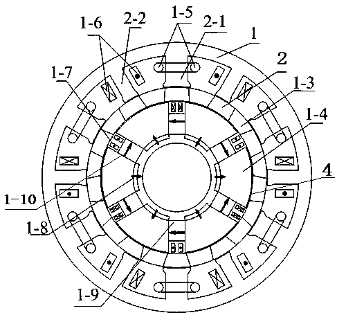
[0023] Such as figure 1 As shown, the present invention includes an outer stator 1, an intermediate rotor 2 and an inner stator 4, the outer stator 1 is coaxially sleeved outside the intermediate rotor 2, the intermediate rotor 2 is coaxially sleeved outside the inner stator 4, the outer stator 1, the inner stator 4 and Radial air gaps are left between the intermediate rotors 2, so the present invention has two layers of radial air gaps. The radial air gaps between the intermediate rotor 2 and the inner stator 4 and the outer stator 1 on the inner and outer sides are equal, and the air gap ranges from 0.4 to 0.6 mm.

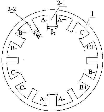
[0024] recombine figure 2 , the outer stator 1 is composed of armature teeth 2-1, excitation teeth 2-2, armature windings 1-5 and outer DC excitation windings 1-6, and the inner surface of the stator yoke of the outer stator 1 is uniformly arranged with armatures along the circumferential direction The tooth 2-1 and the field tooth 2-2, the armature tooth 2-1 ...


PUM


Abstract

The invention discloses a double-end hybrid excitation stator-partition-type flux switching motor. The inner surface of a stator yoke of an external stator is provided with armature teeth and excitation teeth alternately at intervals in circumference direction; each armature tooth is wound by an armature winding, and each excitation tooth is wound by an external DC excitation winding; a stator core of an internal stator is uniformly provided with inner stator slots, the number of which is same with that of the armature teeth, in the circumference direction; the inner side of each inner stator slot is embedded by a non-rare-earth ferrite permanent magnet; the outer side of each inner stator slot is placed by an internal DC excitation winding; a stator core between every two inner stator slots is embedded by a rare-earth neodymium-iron-boron permanent magnet; the external diameter of each rare-earth neodymium-iron-boron permanent magnet is equal to the internal diameter of the non-rare-earth ferrite permanent magnet; and the internal diameter of the rare-earth neodymium-iron-boron permanent magnet is equal to the internal diameter of each inner stator slot. The flux switching motor adopts internal and external stator double-end excitation and realizes flexible control of an air-gap magnetic field, has a broader magnetically-adjusting range and ensures higher torque density and power density of the motor.

Description

technical field [0001] The invention relates to a permanent magnet motor structure, in particular to a mixed excitation magnetic flux switching permanent magnet motor, which belongs to the field of motor manufacturing. Background technique [0002] Due to the limitation of permanent magnet materials, the air gap magnetic field of traditional permanent magnet motors is difficult to adjust, and it is difficult to realize the wide speed regulation operation of the motor, which limits the application of permanent magnet motors in electric vehicles, aerospace and other wide speed regulation occasions. The hybrid excitation motor can not only inherit many advantages of the permanent magnet motor, but also the air gap magnetic field of the motor is smooth and adjustable. During electric operation, it has the advantages of large starting torque and wide speed regulation range; during power generation operation, it has wide voltage regulation capability or wide range variable speed a...

Claims


Application Information

Patent Timeline
Patent Type & Authority Patents(China)
IPC IPC(8): H02K21/38H02K21/02H02K1/14H02K1/17
CPCH02K1/146H02K1/17H02K21/025H02K21/38Y02T10/64
Inventor 全力李西京朱孝勇张超杜怿项子旋樊德阳
Owner JIANGSU UNIV
Why Eureka
Try Eureka