A hydraulic mold pressure system

A pressure system and hydraulic technology, applied in the field of hydraulic mold pressure system, can solve the problem of the pressure system without the upper cylinder, and achieve the effect of meeting the requirements of use, simple structure, and simplifying the difficulty of debugging

Active Publication Date: 2018-10-19
CHUZHOU MODERN MOLD MFG
View PDF6 Cites 0 Cited by
  • Summary
  • Abstract
  • Description
  • Claims
  • Application Information

AI Technical Summary

Problems solved by technology

[0003] At present, there are only two pressure systems of the main cylinder and the lower cylinder in the ordinary hydraulic press, but no pressure system of the upper cylinder.

Method used


Image

  • A hydraulic mold pressure system
  • A hydraulic mold pressure system

Examples


Embodiment Construction

[0016] The content of the present invention will be described below in conjunction with specific embodiments.

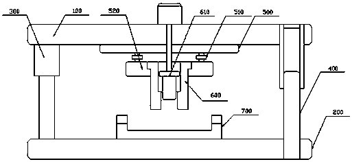
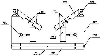
[0017] Such as Figure 1 to Figure 2 Shown is a schematic structural diagram of a hydraulic mold pressure system according to the present invention.

[0018] A hydraulic mold pressure system according to the present invention includes: an upper mold base 100 and a lower mold base 200, and a hydraulic rod 300 and a piston rod 400 used in conjunction are arranged between the upper mold base 100 and the lower mold base 200, A hydraulic mechanism 500 is arranged below the upper die base 100;

[0019] A transmission cylinder 510 is symmetrically arranged below the hydraulic mechanism 500, and a synchronization module 520 is connected to the transmission cylinder 510. A die punch 600 is arranged on the synchronization module 520, and the middle part of the die punch 600 is provided with a hydraulic mechanism. 500 connected bomb device 610;

[0020] The lower mold base 2...


PUM


Abstract

The invention discloses a hydraulic type mould pressure system. The hydraulic type mould pressure system comprises an upper mould base and a lower mould base; a hydraulic rod and a cooperatively used piston rod are arranged between the upper mould base and the lower mould base; a hydraulic mechanism is arranged below the upper mould base; transmission air cylinders are symmetrically arranged below the hydraulic mechanism; each transmission air cylinder is connected with a synchronous module; a mould punch is arranged on the synchronous module; a material popping device connected with the hydraulic mechanism is arranged at the middle part of each mould punch; a lower mould used cooperatively with the mould punch is arranged on the lower mould base. The hydraulic type mould pressure system is simple in structure, realizes constant, adjustable and quantitative management of pressure, simplifies the mould adjusting difficulty, and meets the actual use requirement.

Description

technical field [0001] The invention relates to a hydraulic mold pressure system, which belongs to the technical field of mold pressure systems. Background technique [0002] There are many stamping products of auto parts drawing, and the shape of the product is usually more complicated. At the same time, due to the specific matching relationship, the dimensional tolerance of the workpiece is very small. Between), put forward high requirements on the mold. Since the raw material is a flat material and the shape of the final product is a three-dimensional shape, the material will undergo a series of changes such as extension, flow, elastic deformation, and plastic deformation during the forming process. In order to prevent the material from being unstable and wrinkling during the stretching process, At the same time, the shape of the product meets the tolerance requirements. The mold must first be supported by the lower ejector cylinder to complete the forming of the parting...

Claims


Application Information

Patent Timeline
Patent Type & Authority Patents(China)
IPC IPC(8): B21D37/10B21D37/12B21D22/20
CPCB21D22/20B21D37/10B21D37/12
Inventor 郭勇
Owner CHUZHOU MODERN MOLD MFG
Why Eureka
Try Eureka