
Electronic expansion valve
An electronic expansion valve, valve seat technology, applied in the direction of lift valve, valve details, valve device, etc., can solve the problems affecting the normal use and deformation of the electronic expansion valve, and achieve the effect of reducing the pressure difference and avoiding the deformation of the valve needle
- Summary
- Abstract
- Description
- Claims
- Application Information
AI Technical Summary
Problems solved by technology
Method used
Image

Examples
Embodiment Construction
[0015] The present invention will be described in detail below with reference to the accompanying drawings and in combination with embodiments.
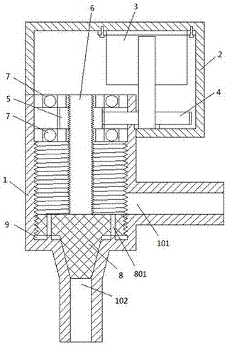
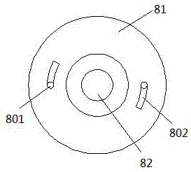
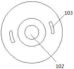
[0016] Such as Figures 1 to 3 As shown, the electronic expansion valve includes a casing 2, a valve seat 1, a valve needle 8, a driving mechanism, and an actuator. The driving mechanism is installed in the casing 2, the actuator is installed in the valve seat 1, and the casing 2 is disassembled and installed on the valve seat 1. Above, the valve needle 8 is connected with the actuator, and the valve needle 8 includes a disc-shaped threaded part 81 and a rounded frustum-shaped blocking part 82. The diameter is smaller than the diameter of the bottom end of the threaded portion 81, and the threaded portion 81 is provided with a through hole 801 that penetrates up and down, and the bottom end of the threaded portion 81 is provided with an arc-shaped groove 802 that communicates with the lower opening of the through hole 801; The valve...
PUM
 Abstract
Description
Claims
Application Information