
A fully automatic cloth cutting equipment
A fully automatic, equipment-based technology, applied in the cutting of textile materials, textiles and papermaking, etc., can solve the problems of high labor intensity and low processing efficiency, and achieve the effects of reducing labor intensity, high processing efficiency, and low cutting accuracy
- Summary
- Abstract
- Description
- Claims
- Application Information
AI Technical Summary
Problems solved by technology
Method used
Image

Examples
Embodiment Construction
[0017] The present invention will be further described in detail below in conjunction with the accompanying drawings and specific embodiments.
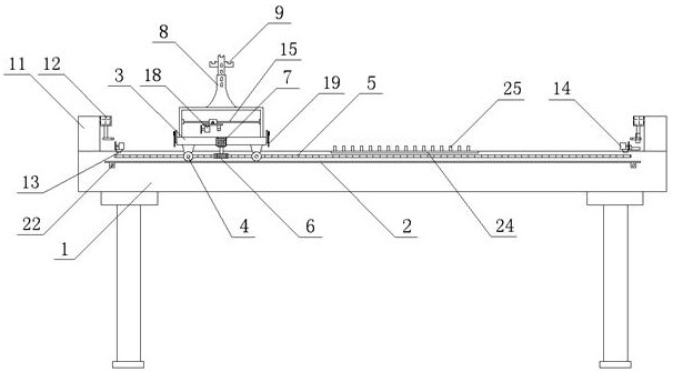
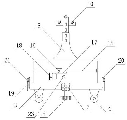
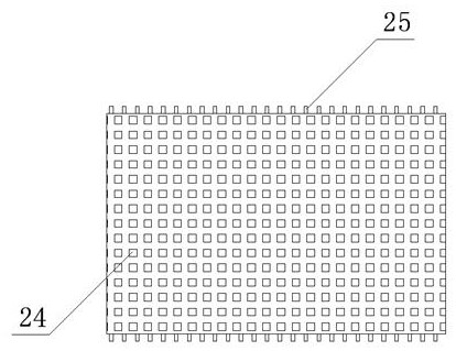
[0018] see Figure 1 to Figure 3 , a fully automatic cloth cutting equipment of the present invention, comprising a cloth platform 1, characterized in that: the bottom side of the cloth platform 1 is horizontally fixed with a side track 2, and the side track 2 is provided with a multifunctional sliding table 3 , the roller 4 installed on the multifunctional sliding table 3 is located on the side rail 2, the side rack 5 is fixed on the side of the pull platform 1 and is parallel to the side rail 2, and a stepper motor is installed on the multifunctional sliding table 3 7. A transmission gear 6 is fixed on the output shaft of the stepping motor 7, and the transmission gear 6 meshes with the side rack 5. A pair of adjustable frames 8 are fixed on one side of the upper surface of the multifunctional sliding table 3. A plurality of reel s...
PUM
 Abstract
Description
Claims
Application Information