Belt tightener for a safety belt system

A technology of seat belts and tensioners, applied in the direction of seat belts, belt tensioners, transportation and packaging in vehicles

Inactive Publication Date: 2017-10-17
TRW AUTOMOTIVE GMBH
View PDF7 Cites 2 Cited by
  • Summary
  • Abstract
  • Description
  • Claims
  • Application Information

AI Technical Summary

Problems solved by technology

[0004] As in all technical devices, even in belt tensioners there are undesired effects which lead to a difference between the energy supplied and the energy available

Method used


Image

  • Belt tightener for a safety belt system
  • Belt tightener for a safety belt system
  • Belt tightener for a safety belt system

Examples


Embodiment Construction

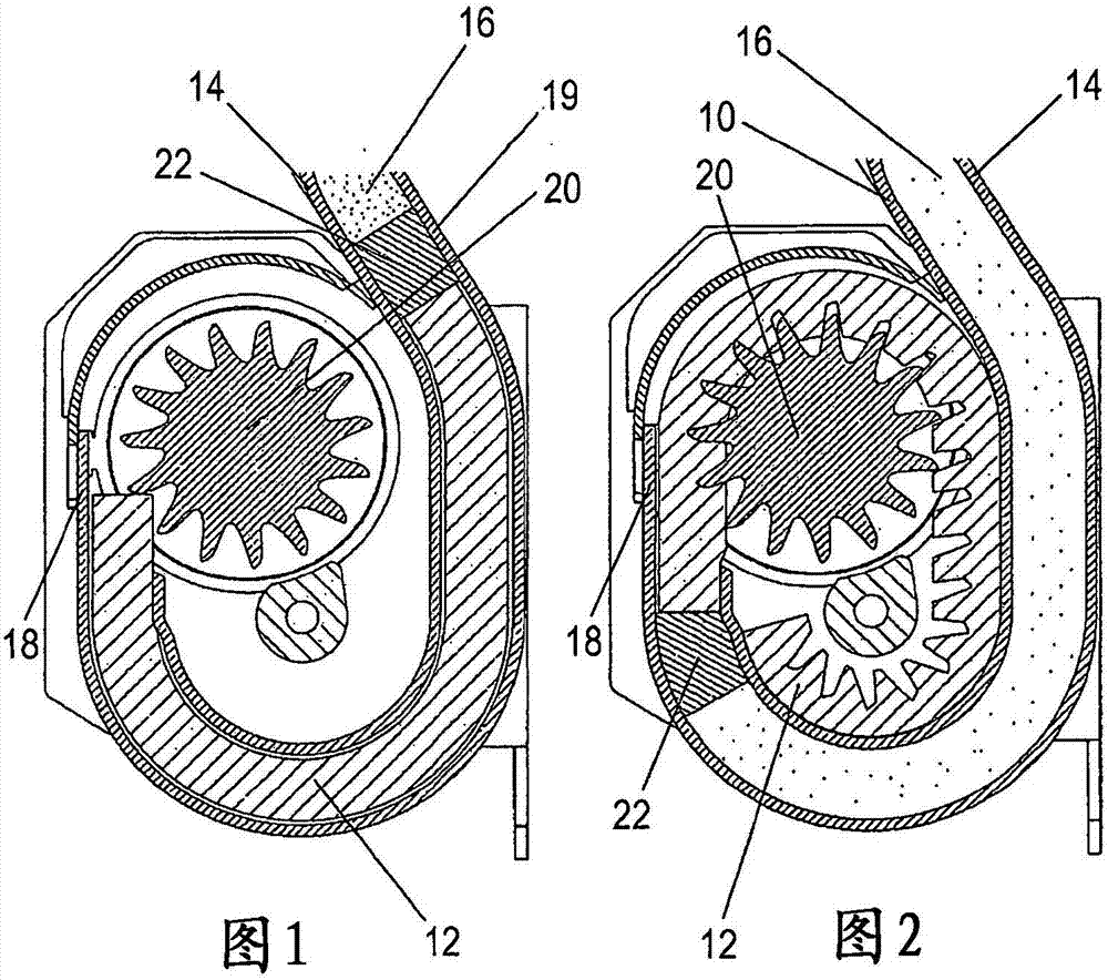
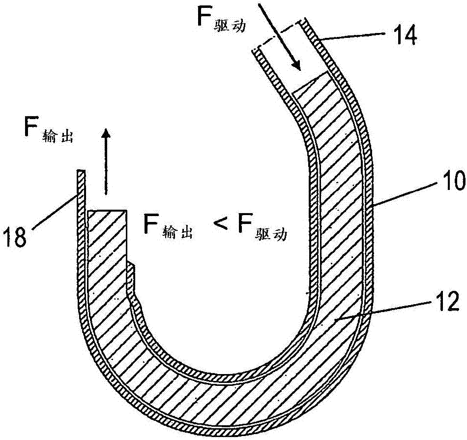
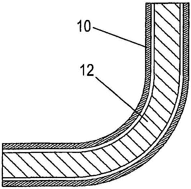
[0035] in figure 1 Shows the driving device of the seat belt tensioner for the seat belt retractor. The drive device has a force transmission element 12 movably arranged in the tensioner tube 10. The force transmission element 12 is made of a substantially deformable material.

[0036] On the first end 14 of the tensioner tube 10, in a section of the tensioner tube 10 serving as a pressure chamber, the compressed gas 16 may be provided by a gas generator (not shown). The second end of the tensioner tube 10 is oriented to the outer toothing of a rotatably supported drive wheel 20, which is coupled to a belt spool of a belt retractor (not shown).

[0037] An elastic sealing element 22 is arranged between the compressed gas 16 and the force transmission element 12, which can also move in the tensioner tube 10. The sealing element 22 rests on the force transmission element 12, but a small distance can also be set. The sealing element 22 holds the compressed gas 16 on the side of the...


PUM


Abstract

A belt tightener for a safety belt system comprises a drive device having a tightener tube (10) and a substantially deformable power transmission element (12) which is guided inside the tightener tube (10) and engages a rotatable drive element during belt tightening. According to the invention, at least part of the surface of the power transmission element (12) and/or at least part of the inner surface of the tightener tube (10) is structured and covered with a lubricant.

Description

Technical field [0001] The invention relates to a seat belt tensioner for a seat belt system, which has a drive device with a tensioner tube and a substantially deformable force transmission element guided in the tensioner tube, The force transmission element engages with the rotatable drive element during the tightening process. Background technique [0002] The seat belt tensioner is used to reduce the adverse effect on the tightening of the occupant in the tightening situation before the vehicle occupant starts to lean forward and use the force limiting device when necessary. The so-called film spool effect (the seat belt is loosely rolled onto the seat belt spool) and seat belt slack (the seat belt does not fit tightly on the occupant) are the effects. The seat belt tensioner reduces seat belt slack and the effect of the film spool in a very short time. The method is as follows: the seat belt tensioner tightens the seat belt. Therefore, the occupants can participate in the ...

Claims


Application Information

Patent Timeline
Patent Type & Authority Applications(China)
IPC IPC(8): B60R22/46
CPCB60R22/4628B60R2022/4642
Inventor A·兰德贝克T·莫丁格A·魏德曼A·普雷吉策
Owner TRW AUTOMOTIVE GMBH
Why Eureka
Try Eureka