Multy-membered heating radiator

A heater and multi-stage technology, applied in the field of a multi-stage heater, can solve the problems of internal leakage, failure to ensure that the flow of heat-carrying medium is only controlled by the built-in valve, and leakage

Inactive Publication Date: 2009-01-21
DANFOSS AS
View PDF0 Cites 0 Cited by
  • Summary
  • Abstract
  • Description
  • Claims
  • Application Information

AI Technical Summary

Problems solved by technology

[0003] In this structure, there is a risk of leakage, especially internal leakage, so it cannot be guaranteed that the heat transfer medium flow is only controlled by the built-in valve

Method used


Image

  • Multy-membered heating radiator
  • Multy-membered heating radiator
  • Multy-membered heating radiator

Examples


Embodiment Construction

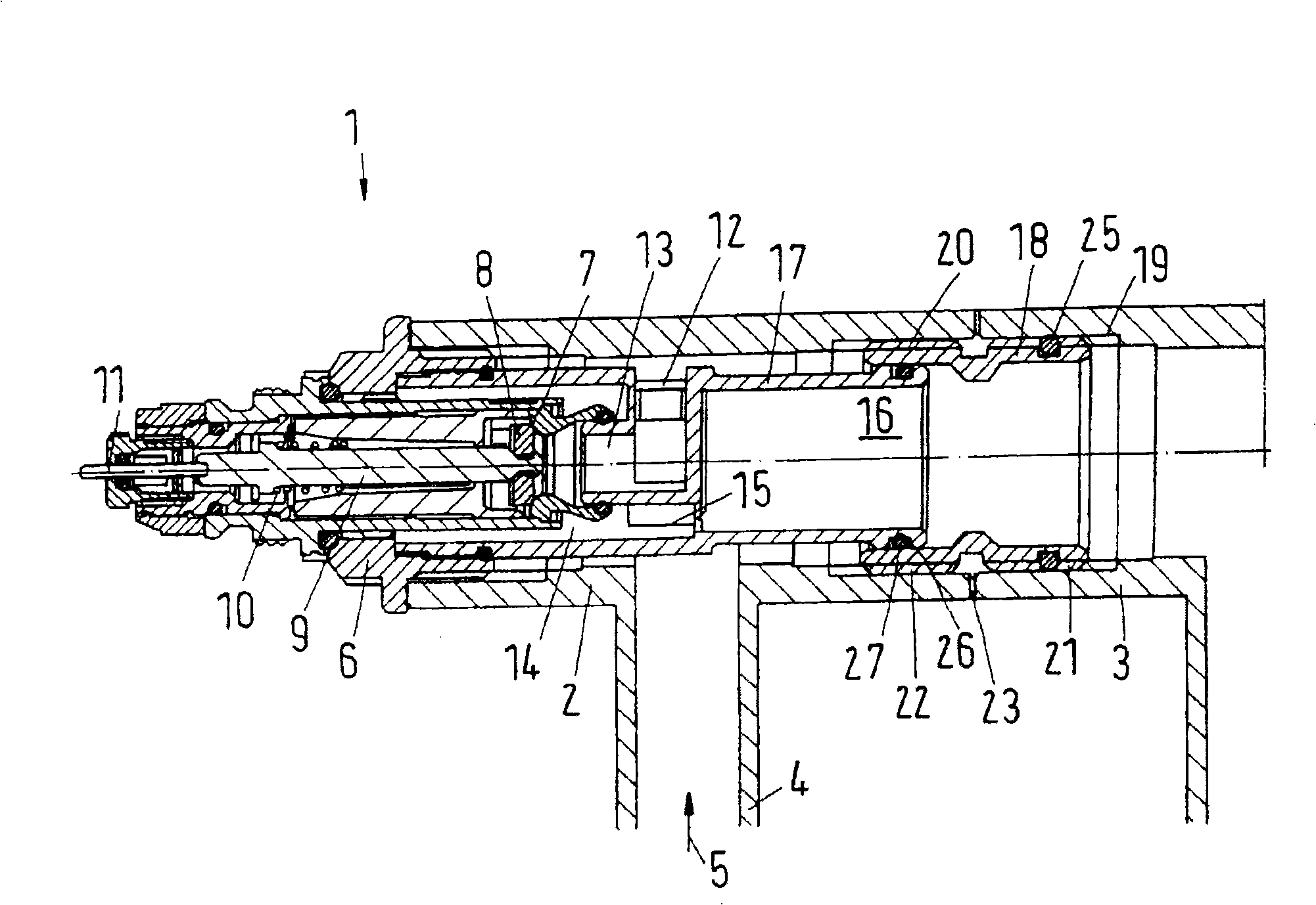
[0023] The multi-section heater 1 has a first section 2 and a second section 3 . Further segments can be connected to the second segment 3 in a well-known manner not shown in detail,

[0024] The first section 2 serves as a pressure duct through which a heat transfer medium, for example hot water, flows in the direction of the arrow 5 .

[0025] In order to control the heat transfer medium, an integral valve 6 is screwed into the first section 2 . The built-in valve 6 has a valve seat 7 with which a valve part 8 cooperates. The valve element 8 is fastened to a push rod 9 which is biased away from the valve seat 7 by an opening spring 10 . The push rod 9 is actuated by an actuating pin 11 , usually acting on a thermostat valve cover (not shown in detail), in such a way that it presses the valve part 8 again in the direction of the valve seat 7 . Therefore, the distance between the valve element 8 and the valve seat 7 determines the volumetric flow rate of the heat transfer m...


PUM


Abstract

The invention relates to a multi-section heater (1) which comprises multiple sections (2, 3) that are connected in series through connectors (18) and are sealed from the outside in the connection area though the sealing devices (23). The first section (2) is equipped with a build-in valve (6) extended to the connector (18) between the first section (2) and the second section (3); the connector (18) between the first section (2) and the second section (3) has at least one screw (19, 20) used for connecting one of the two sections (2, 3). The screw (19) is has a screw seal device (25) for ensuring that the heat carrier is only controlled by the built-in valve (6).

Description

technical field [0001] The invention relates to a multi-section heater, comprising a plurality of sections, which are respectively connected to each other in series by couplings, and are respectively sealed externally by a sealing device in their connection areas, wherein the first section has a built-in A valve extending up to a coupling between the first and second sections, and a coupling between the first and second sections having at least one for connection to one of the two sections of thread. Background technique [0002] A multi-section heater of this type is known from Italian patent 01300587. When the coupling is clamped, the seals between the segments are compressed. The built-in valve extends a tube into the coupling between the first section and the second section. A seal seals between the tube and the coupling. [0003] In this construction there is a risk of leakage, especially internal leakage, so that it cannot be guaranteed that the flow of the heat tr...

Claims


Application Information

Patent Timeline
Patent Type & Authority Applications(China)
IPC IPC(8): F24H7/02F24H9/14
CPCF24D19/0012F28F9/264
Inventor 詹姆斯·梅斯默泽伦·H·泽伦森克里斯琴·阿格斯贝克
Owner DANFOSS AS
Why Eureka
Try Eureka