Image encoding device and method, image decoding device and method, and image transmission system
An image encoding and image decoding technology, which is applied in the field of image encoding equipment, image decoding equipment and image transmission system, can solve the problem of increasing the amount of encoded data, etc.
- Summary
- Abstract
- Description
- Claims
- Application Information
AI Technical Summary
Problems solved by technology
Method used
Image

Examples
no. 1 approach
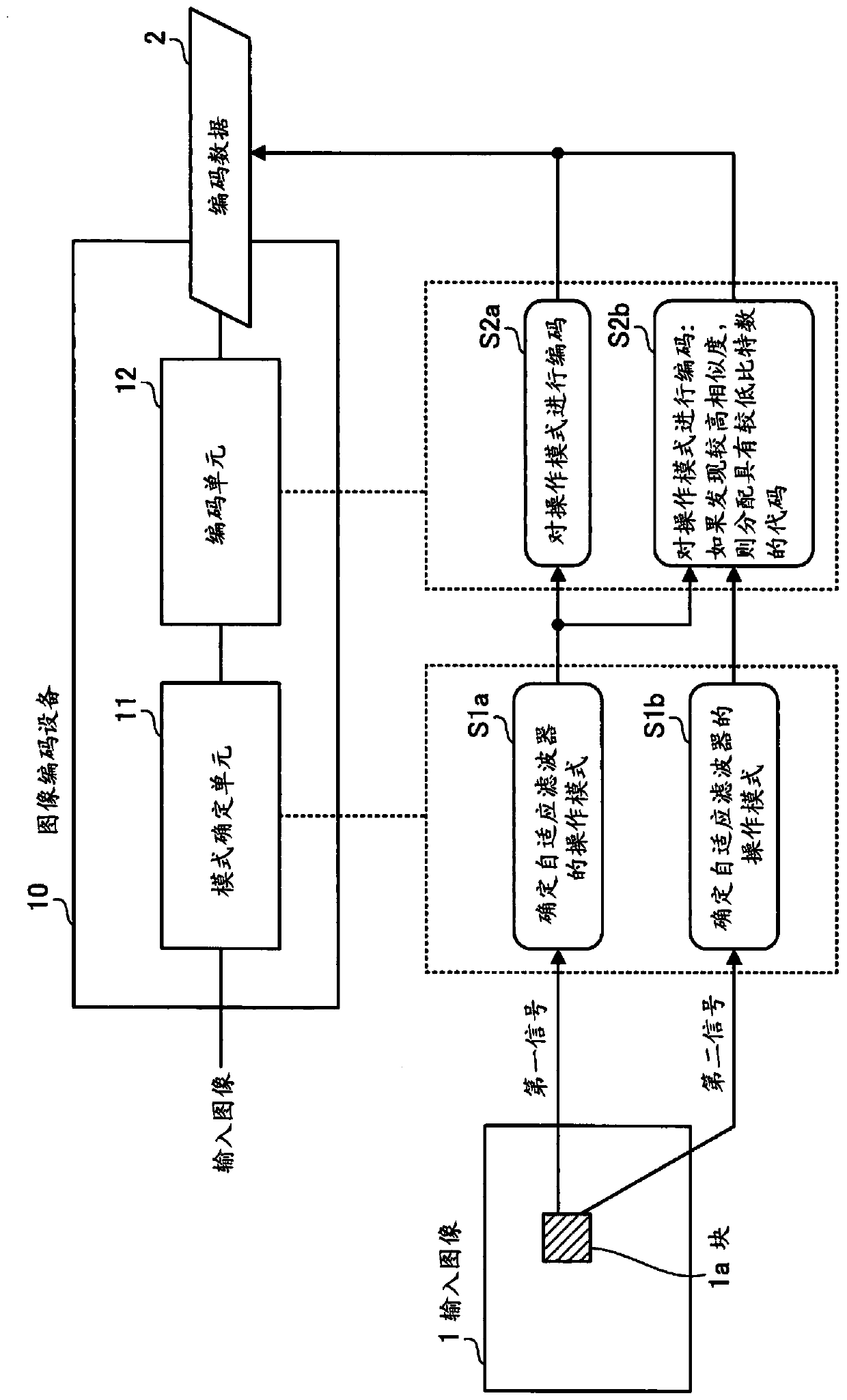
[0031] figure 1 A configuration and processing example of the image coding device according to the first embodiment are shown. The image encoding device 10 is a device for generating encoded data by encoding an input image that is video. We assume the case where an input image 1 is input and encoded data 2 is output. The image encoding device 10 includes a mode determination unit 11 and an encoding unit 12 . The mode determination unit 11 and the encoding unit 12 are realized as, for example, semiconductor circuits. At least a part of the processing of the mode determination unit 11 and the encoding unit 12 can be realized by a processor executing a predetermined program.
[0032] The mode determination unit 11 determines a first operation mode and a second operation mode of the adaptive filter applied to the encoding target block 1 a in the input image 1 at the time of decoding. The mode determination unit 11 determines the first operation mode based on the first signal o...
no. 2 approach
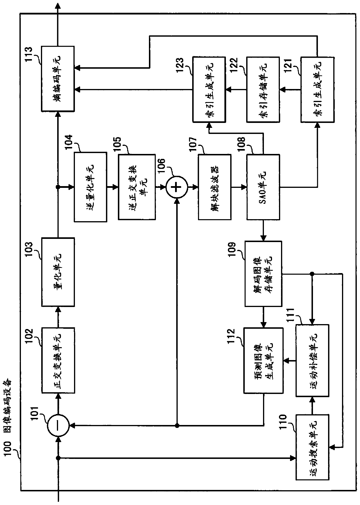
[0038] Next, the second embodiment relates to an image encoding device and an image decoding device that respectively perform encoding and decoding of video in HEVC. figure 2 A configuration example of an image encoding device according to the second embodiment is shown. The image coding apparatus 100 includes a prediction error signal generation unit 101, an orthogonal transformation unit 102, a quantization unit 103, an inverse quantization unit 104, an inverse orthogonal transformation unit 105, a decoded image generation unit 106, a deblocking filter 107, an SAO unit 108, A decoded image storage unit 109 , a motion search unit 110 , a motion compensation unit 111 , a predicted image generation unit 112 , and an entropy encoding unit 113 .
[0039] Each picture of video data input to the image encoding device 100 is divided into blocks. The prediction error signal generation unit 101 acquires an encoding target block, and calculates a difference between the acquired encod...
no. 3 approach
[0180] The image encoding device 100 and the image decoding device 200 according to the second embodiment, the first modification, or the second modification described above, for example, by combining them into Figure 20 The image transmission system shown is implemented. Figure 20 A configuration example of an image transmission system according to the third embodiment is shown. The image transmission system includes an image transmission system 410 for generating and transmitting a video stream and an image reception system 420 for receiving and decoding the video stream.
[0181] The image transmission system 410 includes, for example, an image input device 411 , an image encoding device 412 , and a transmission device 413 . The image input device 411 supplies video baseband data to the image encoding device 412 . For example, the image input device 411 may be a camera for capturing and outputting an image or a device for outputting image data previously stored in a sto...
PUM
 Abstract
Description
Claims
Application Information
 - R&D
- Intellectual Property
- Life Sciences
- Materials
- Tech Scout
- Unparalleled Data Quality
- Higher Quality Content
- 60% Fewer Hallucinations
Browse by: Latest US Patents, China's latest patents, Technical Efficacy Thesaurus, Application Domain, Technology Topic, Popular Technical Reports.
© 2025 PatSnap. All rights reserved.Legal|Privacy policy|Modern Slavery Act Transparency Statement|Sitemap|About US| Contact US: help@patsnap.com