A kind of ceiling system and installation method

An installation method and a suspended ceiling technology, which are applied to ceilings, building components, buildings, etc., can solve the problems of poor painting effect of painters, low construction efficiency, complicated installation links, etc., and achieve accurate shape and size, simplified installation steps, and good molding effect Effect

Active Publication Date: 2018-07-20
CHENGDU CONSTR ENG DECORATION & FITMENT CO LTD
View PDF5 Cites 0 Cited by
  • Summary
  • Abstract
  • Description
  • Claims
  • Application Information

AI Technical Summary

Problems solved by technology

[0004] The purpose of the present invention is to overcome the above-mentioned deficiencies of the existing ceiling system with a groove shape, the installation process is complicated, the painter’s coating effect is poor, the disassembly is very troublesome, the construction efficiency is low, and the adaptability is poor, etc., to provide a ceiling system and installation method

Method used


Image

  • A kind of ceiling system and installation method
  • A kind of ceiling system and installation method
  • A kind of ceiling system and installation method

Examples


Embodiment 1

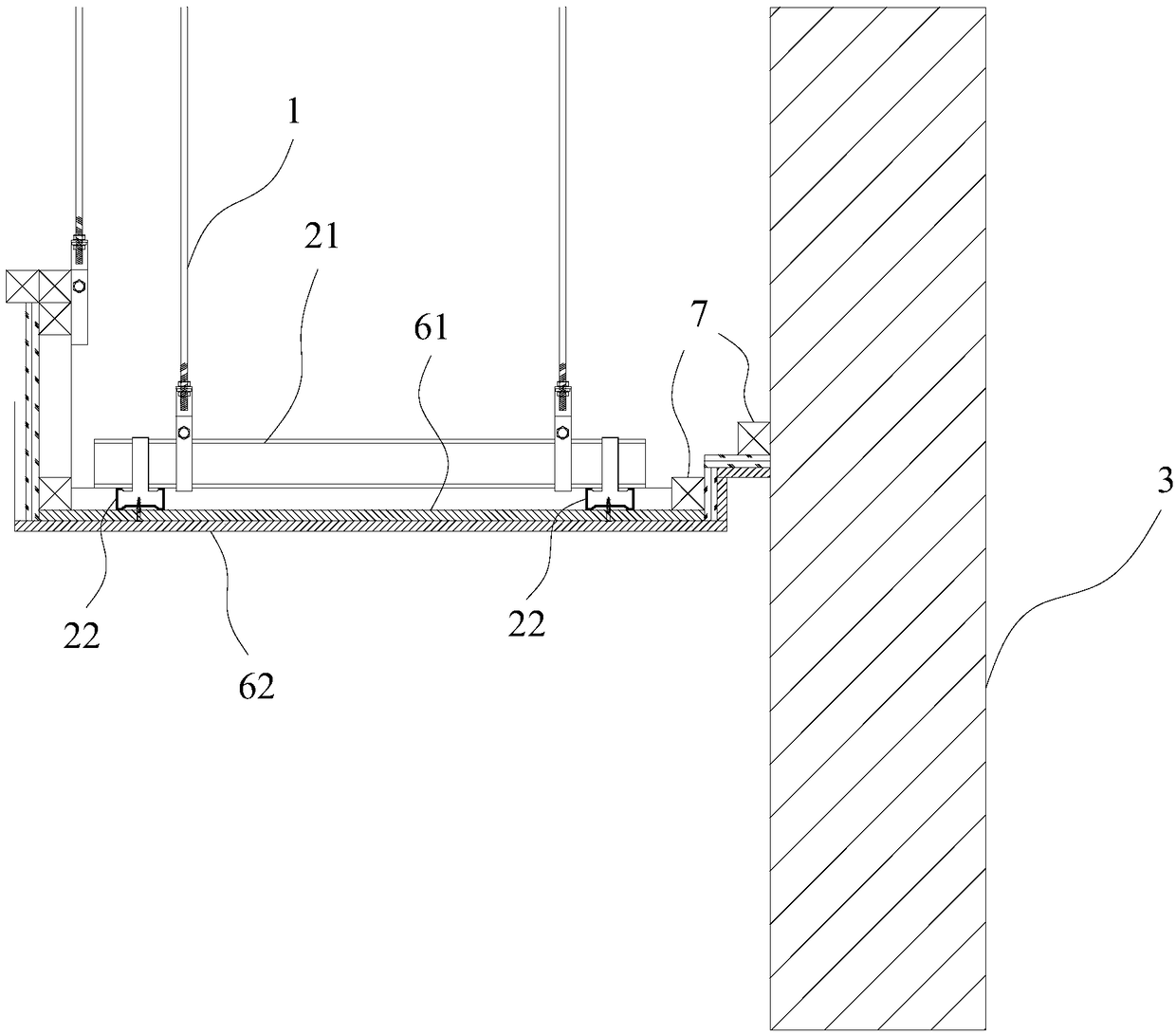
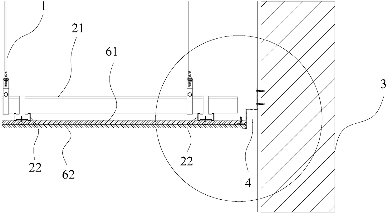
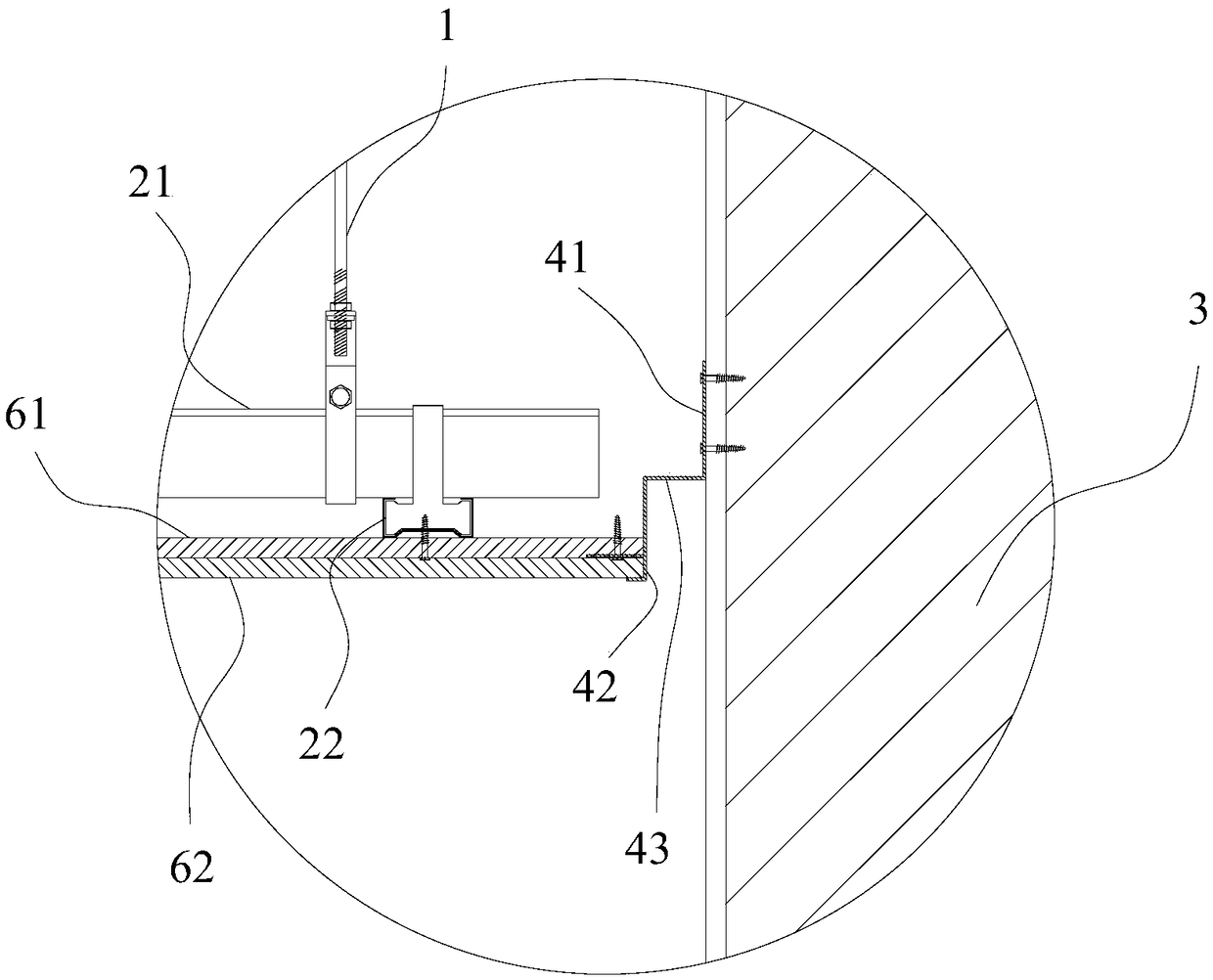
[0038] Such as Figure 2-4As shown, a ceiling system includes a suspender 1, a keel and a cover panel, the keel includes a main keel 21, a secondary keel 22 and a side keel 4, the main keel 21 is connected to the floor through the suspender 1, and the The secondary keel 22 is connected below the main keel 21, the cover panel is connected below the secondary keel 22, the side keel 4 is arranged along the wall 3, and the side keel 4 includes a fixed end 41 and a free end 42. And connecting section 43, described fixed end 41 and free end 42 are connected through described connecting section 43, and described fixed end 41 is used for connecting wall body 3, and described fixed end 41 connects one side of described wall body 3 and The surface shape of the wall 3 is adapted, the wall 3 is a vertical plane wall, the fixed end 41 is also straight along the length direction, and there is a gap between the cover panel and the wall 3, so The fixed end 41, the free end 42 and the connect...

Embodiment 2

[0040] Such as Figure 5-6 As shown, the structure of a suspended ceiling system of the present invention is roughly the same as that of Embodiment 1. The difference from Embodiment 1 is that the connecting section 43 of the side keel 4 is arc-shaped, and the side keel 4 forms S-shaped structure.

Embodiment 3

[0042] A method for installing a suspended ceiling system, comprising using a suspended ceiling system as in Embodiment 1 or 2, the installation method comprising the following steps:

[0043] Step 1, install the boom 1;

[0044] Step 2, install the main keel 21 under the boom 1, and install the secondary keel 22 under the main keel 21;

[0045] Step 3, install the side keel 4 along the wall 3;

[0046] Step 4: Install a cover panel under the secondary keel 22 .

[0047] First, the line is snapped and the height of the suspended ceiling is determined, and then the boom 1 is fixed with expansion bolts, then the main keel 21 is hung on the boom 1 and leveled, and then the secondary keel 22 is connected to the Below the main keel 21, the main keel 21 and the secondary keel 22 are perpendicular to each other, then the secondary keel is installed, the fixed end 41 is fixed along the wall 3 with several self-tapping screws, and then the cover is installed The base member 61 of th...


PUM


Abstract

The invention discloses a ceiling system and a mounting method. Edge keels do not need to be manufactured and assembled on site, on-site shearing splicing of square wood laminated plates and the likeis avoided, convenient and rapid effects are achieved, the mounting steps are simplified, and the forming effect is good; in mounting, the splicing frequency can be decreased, the construction progress is accelerated, and the labor cost is saved; the visual impression is improved effectively, the height and position relations between the edge keels and a main keel as well as the edge keels and subkeels are controlled and adjusted conveniently, and the modeling size is accurate; the applicability is wide, the situation that gaps are internally coated again after mounting is avoided, the mounting and dismounting steps are simple and rapid, and the mounting efficiency is greatly improved; and the potential safety hazard caused due to the fact that the adhesion connecting positions of the multiple laminated plates crack or square woods are perished after long-time use is avoided.

Description

technical field [0001] The invention relates to the field of building engineering construction, in particular to a ceiling system and an installation method. Background technique [0002] With the advancement and development of science and technology, people's needs are gradually increasing, and they are increasingly pursuing complex and changeable interior space shapes. When designing and constructing existing indoor ceilings, in order to make the whole more beautiful, the shade between the ceiling and the wall The position of the line appears smoother to avoid cracking and deformation at the connection between the ceiling and the wall. At the same time, objects that can hide and arrange light strips and other objects that increase the sense of interior space design are arranged. A circle of grooves is often set along the edge of the wall to transform the inner corner into a The positive angle improves the visual perception and increases the three-dimensionality of the desi...

Claims


Application Information

Patent Timeline
Patent Type & Authority Patents(China)
IPC IPC(8): E04B9/06E04B9/18E04B9/22E04G21/14
CPCE04B9/06E04B9/18E04B9/22E04G21/14
Inventor 薛庆文范云珍陈波王鹏强陈军罗阳
Owner CHENGDU CONSTR ENG DECORATION & FITMENT CO LTD
Why Eureka
Try Eureka