A paint spraying device
A spraying device and paint technology, applied in the direction of spraying device, etc., can solve the problems of poor paint application effect, operator injury, low work efficiency, etc., so as to improve work efficiency, improve painting effect, and avoid repeated painting. Effect
- Summary
- Abstract
- Description
- Claims
- Application Information
AI Technical Summary
Problems solved by technology
Method used
Image
Examples
specific Embodiment approach 1
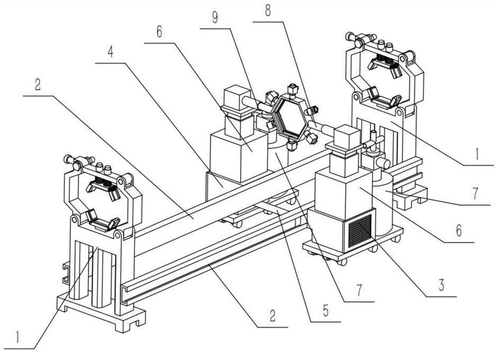
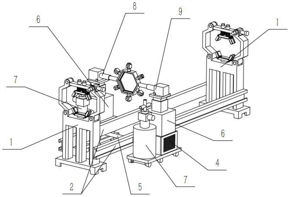
[0042] Combine below Figure 1-19 In this embodiment, a paint spraying device includes a sliding frame 2, a driving mechanism 5, and a liquid control mechanism 6. The paint spraying device also includes a fixing mechanism 1, a left moving mechanism 3, a right moving mechanism 4, and a liquid supply mechanism. 7. The left spraying mechanism 8 and the right spraying mechanism 9, the fixing mechanism 1 is provided with two, the sliding frame 2 is provided with two, and the two ends of the two sliding frames 2 are fixedly connected to the ends of the two fixing mechanisms 1 respectively. Left and right ends, the left moving mechanism 3 and the right moving mechanism 4 are respectively fixedly connected to the left and right ends of the two sliding frames 2, and the two ends of the driving mechanism 5 are respectively arranged on the left moving mechanism 3 and the right In the moving mechanism 4, there are two hydraulic control mechanisms 6, and the two hydraulic control mechanism...
specific Embodiment approach 2
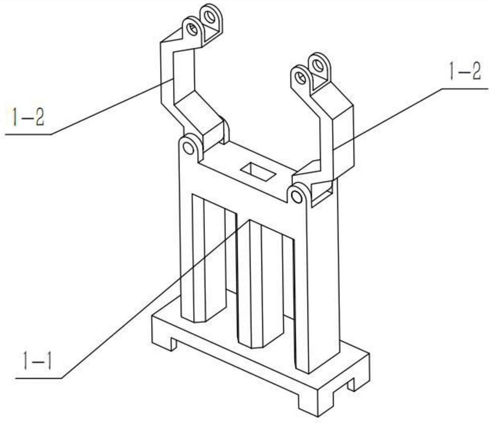
[0044] Combine below Figure 1-19 Describe this embodiment, this embodiment will further explain the first embodiment, the fixing mechanism 1 includes a support frame 1-1, a support rod 1-2, a bottom frame 1-3, a side frame 1-4, and a spring shaft 1-5 , limit bar 1-6, bolt group 1-7, top frame 1-8, slide bar 1-9 and spring 1-10, described support bar 1-2 is provided with two, two support bars 1-2 They are respectively hinged on the left and right sides of the upper end of the support frame 1-1, the bottom frame 1-3 is fixedly connected to the upper end of the support frame 1-1, and the limit rod 1-6 is hinged on the left side of the support rod 1-2. At the upper end, the bolt group 1-7 runs through the right end of the limit rod 1-6 and the upper end of the right support rod 1-2, and two of the sliding rods 1-9 are fixed, and the two sliding rods 1-9 are fixed Connected to the upper end of the top frame 1-8, and the two sliding rods 1-9 are slidably connected to the limit rod...
specific Embodiment approach 3
[0047] Combine below Figure 1-19 Describe this embodiment, this embodiment will further explain the second embodiment, the sliding frame 2 includes a sliding tube 2-1 and a sliding block 2-2, and the sliding block 2-2 is slidably connected in the sliding tube 2-1 , the two ends of the two sliding tubes 2-1 are respectively fixedly connected to the left and right sides of the middle part of the two support frames 1-1, and the two sliding blocks 2-2 are respectively connected with the left moving mechanism 3 and the right moving mechanism 4 Fixed connection.
PUM
 Abstract
Description
Claims
Application Information
 - R&D
- Intellectual Property
- Life Sciences
- Materials
- Tech Scout
- Unparalleled Data Quality
- Higher Quality Content
- 60% Fewer Hallucinations
Browse by: Latest US Patents, China's latest patents, Technical Efficacy Thesaurus, Application Domain, Technology Topic, Popular Technical Reports.
© 2025 PatSnap. All rights reserved.Legal|Privacy policy|Modern Slavery Act Transparency Statement|Sitemap|About US| Contact US: help@patsnap.com


