Antenna control method and device

An antenna control method and antenna technology, applied in antennas, antenna parts, diversity/multi-antenna systems, etc., can solve the problems of UAV navigation angle, direction signal interruption, and small coverage of UAV single antenna

Active Publication Date: 2021-04-27
POWERVISION ROBOT INC
View PDF4 Cites 0 Cited by
  • Summary
  • Abstract
  • Description
  • Claims
  • Application Information

AI Technical Summary

Problems solved by technology

[0004] The embodiment of the present invention provides an antenna control method and device to solve the problem that the single antenna coverage of the prior art unmanned aerial vehicle is small, and the unmanned aerial vehicle is easily interrupted by the influence of the navigation angle and direction, etc.

Method used


Image

  • Antenna control method and device
  • Antenna control method and device
  • Antenna control method and device

Examples


Embodiment 1

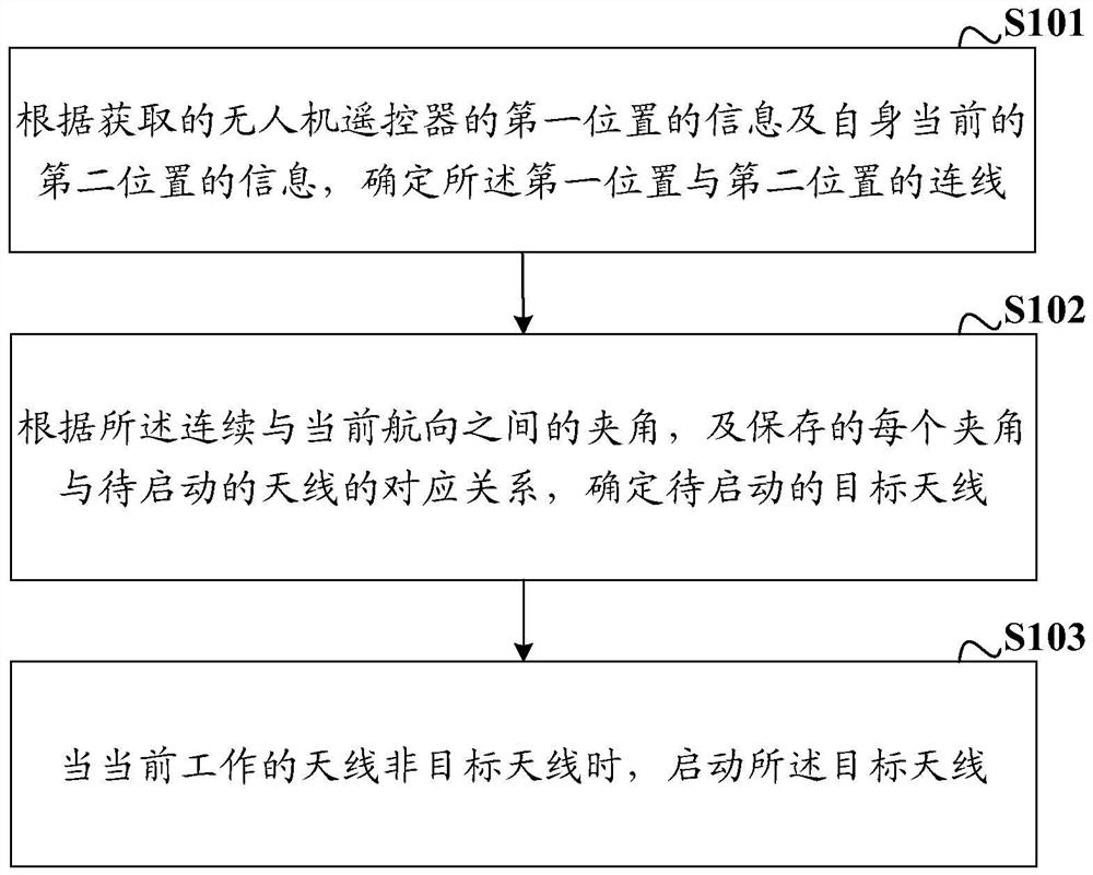
[0043] see figure 1 As shown, a schematic flowchart of an antenna control method provided by an embodiment of the present invention, a specific implementation method includes:

[0044] S101: Determine the connection between the first position and the second position according to the acquired information of the first position of the remote controller of the drone and the information of the current second position of the drone.

[0045] The antenna control method provided by the embodiment of the present invention is applied to an unmanned aerial vehicle. The unmanned aerial vehicle is a multi-antenna unmanned aerial vehicle, and the working range of two or more antennas on the unmanned aerial vehicle covers 360° of the unmanned aerial vehicle. range. The information of the first position of the remote controller of the drone and the information of the current second position of the drone obtained in this embodiment may be the latitude and longitude information of the first pos...

Embodiment 2

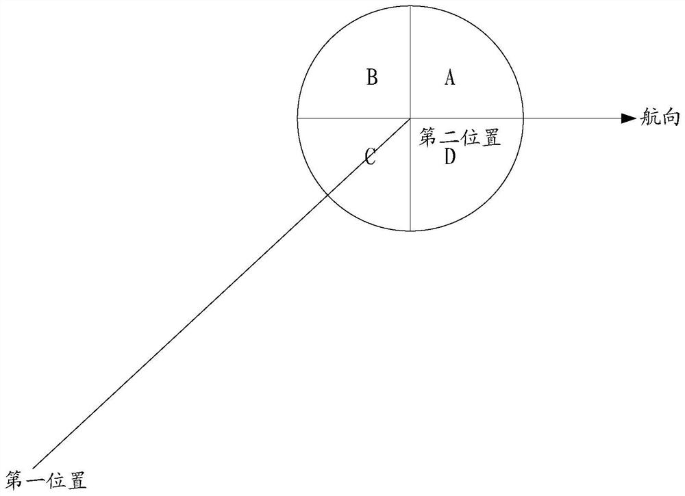
[0056] In this embodiment of the present invention, in order to improve the accuracy of determining the target antenna to be activated, the process of determining the angle between the connection line and the current heading includes:

[0057] Constructing a coordinate system with the second position as the pole and the heading as the polar axis;

[0058] Determine the angle between the connecting line and the polar axis.

[0059] Specifically, a coordinate system is constructed by taking the second position of the drone itself as the pole and the current heading of the drone as the polar axis, and determining the connection between the second position of the drone itself and the first position of the remote controller of the drone and the polar axis. angle.

[0060] A map including the first position and the second position is saved in the drone. The drone can determine the connection between the first position and the second position on the map, and obtain the current headi...

Embodiment 3

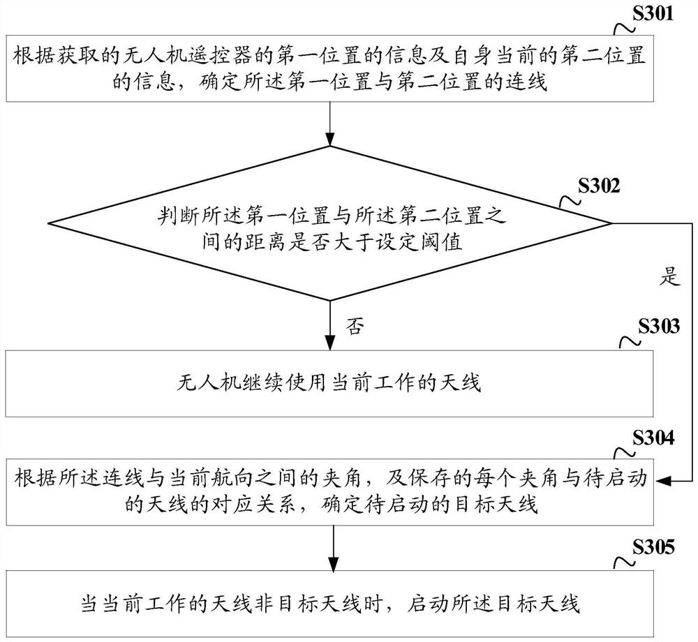
[0079] In this embodiment of the present invention, in order to further ensure the stability and reliability of signal transmission, on the basis of the foregoing Embodiment 1, the method described in this embodiment of the present invention further includes:

[0080] When the angle between the connection line and the current heading cannot be obtained, determine whether the currently working antenna is the set antenna;

[0081] If not, activate the set antenna.

[0082] Wherein, the angle between the connection line and the current heading that cannot be obtained includes at least one of the following:

[0083] Unable to obtain the information of the first position of the remote control of the drone, unable to obtain the information of its current second position and unable to obtain the current heading.

[0084] In the embodiment of the present invention, when the drone cannot obtain one or more of the information of the first position of the remote controller of the drone,...


PUM


Abstract

The invention discloses an antenna control method and device, which are applied to unmanned aerial vehicles. The method includes: determining the first The connection line between the position and the second position; according to the angle between the connection line and the current heading, and the corresponding relationship between each angle and the antenna to be activated, determine the target antenna to be activated; when the current working When the antenna is not the target antenna, activate the target antenna. In the embodiment of the present invention, the target antenna to be activated is determined according to the different angles between the first position of the remote control of the drone and the current second position of the drone and the heading of the drone. In the technology, the coverage of a single antenna of a UAV is small, and the UAV is easily affected by the angle, direction, etc., which may cause signal interruption.

Description

technical field [0001] The present invention relates to the technical field of unmanned aerial vehicles, and in particular, to an antenna control method and device. Background technique [0002] UAVs have developed rapidly in recent years and have been favored by various countries. They are widely used in military fields such as battlefield reconnaissance and enemy situation reconnaissance. However, the work of the UAV is mainly realized by the image acquisition equipment, remote sensing equipment, and infrared equipment carried on the UAV. The information collected by these devices needs to be transmitted to the remote control end of the UAV through the antenna. Therefore, the quality of wireless transmission is high. Whether it is good or bad is an important factor to ensure the transmission quality of the collected information. [0003] The existing UAV transmits signals through a single antenna, but the signal of a single antenna can only cover a certain angle. When the...

Claims


Application Information

Patent Timeline
Patent Type & Authority Patents(China)
IPC IPC(8): H04B7/06H04B7/08H01Q1/28
CPCH01Q1/285H04B7/0602H04B7/0604H04B7/0805
Inventor 郑卫锋其他发明人请求不公开姓名
Owner POWERVISION ROBOT INC
Why Eureka
Try Eureka