Full-automatic optical detection machine for LED substrate

An LED substrate and optical detection technology, which is applied in the direction of optical testing of flaws/defects, material analysis through optical means, and measurement devices, can solve problems such as increasing substrate handling costs, consuming testing time, and reducing testing efficiency, etc., to achieve The effect of simple structure, convenient operation and simple structure

Inactive Publication Date: 2018-03-23
DONGGUAN UNIV OF TECH
View PDF0 Cites 6 Cited by
  • Summary
  • Abstract
  • Description
  • Claims
  • Application Information

AI Technical Summary

Problems solved by technology

[0003] Most of the existing optical inspection equipment for LED substrates uses a conveyor belt as the conveying device, and a detection device is installed above the middle of the belt. The detection device detects the LED substrate on the conveyor belt. There are certain defects in

Method used


Image

  • Full-automatic optical detection machine for LED substrate
  • Full-automatic optical detection machine for LED substrate
  • Full-automatic optical detection machine for LED substrate

Examples


Embodiment Construction

[0032] In order to make those skilled in the art better understand the technical solutions of the present invention, the present invention will be described in detail below with reference to the accompanying drawings. The description in this part is only exemplary and explanatory, and should not have any limiting effect on the protection scope of the present invention. .

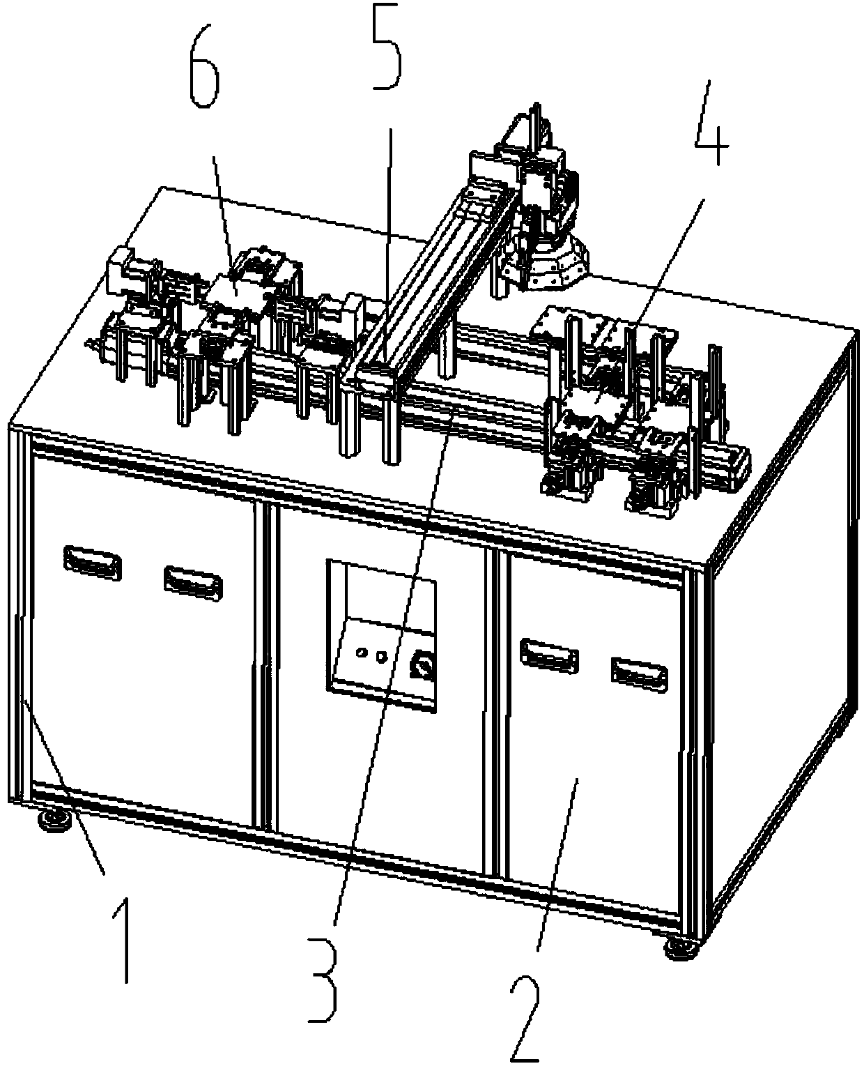
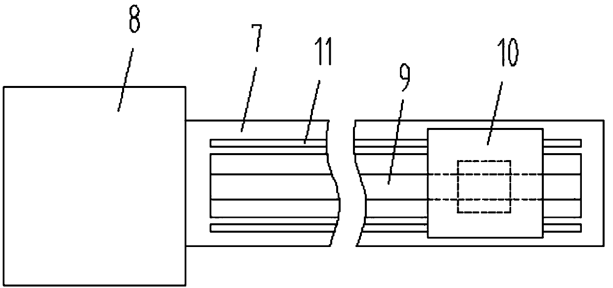
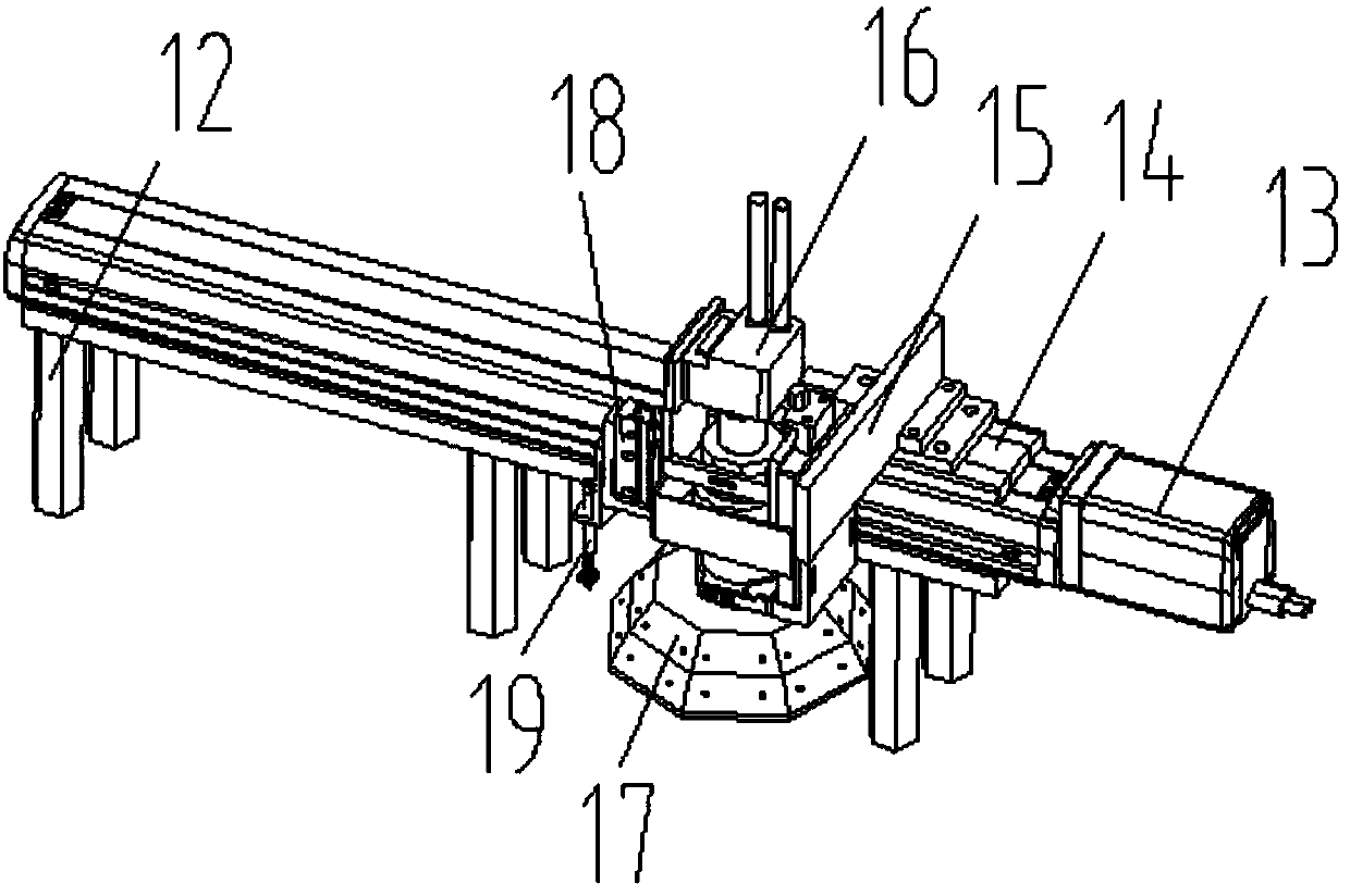
[0033] like Figure 1-Figure 5As shown, the specific structure of the present invention is: an automatic optical inspection machine for LED substrates, which includes a frame 1 and a power distribution control box 2 arranged thereon, and the frame 1 is provided with left-right direction and the substrate 30-matching and reciprocating conveying device 3, above the middle of the conveying device 3 is provided with a detection device 5 that cooperates with the base plate 30, and the left side of the detection device 5 is provided with a base plate 30 that cooperates with the conveying device 3. The flipping de...


PUM


Abstract

The invention relates to a full-automatic optical detection machine for an LED substrate. The full-automatic optical detection machine for the LED substrate comprises a machine frame and a power distribution control cabinet. A conveying device is arranged on the machine frame, a detection device which is matched with the substrate (30) is arranged above the middle of the conveying device, and a turnover device is arranged on the left side of the detection device. The turnover device comprises a material obtaining and lifting device. Turnover bases are arranged on the portions, located on the left side and the right side of the material obtaining and lifting device, of the machine frame, turnover moving cylinders are arranged on the turnover bases and connected with turnover motors, the turnover motors are connected with turnover clamping cylinders, and the turnover clamping cylinders are connected with the turnover clamping blocks. According to the full-automatic optical detection machine for the LED substrate, the conveying device which can conduct reciprocating movement is adopted to conduct conveying, the detection device is arranged in the middle of the conveying device, the turnover device which is matched with the substrate on the conveying device is arranged on the left side of the detection device, and therefore turnover of the substrate is achieved through the turnoverdevice, then the detection efficiency is greatly improved, the detected substrate can return to the position where the substrate is placed, and the handling cost of the substrate is greatly reduced.

Description

technical field [0001] The invention relates to the field of LED basic detection equipment, in particular to a fully automatic optical detection machine for LED substrates. Background technique [0002] The application of LED lights is becoming more and more extensive, and the demand is increasing, and the key of LED lights is the LED substrate. There are many welding points on the LED substrate, and the LEDs basically have some matching holes, and there are card slots on the front and rear sides. , and in the production process of LED substrates, it is often necessary to perform optical inspection on the solder joints, that is, to detect whether the solder joints are all in an accurate position through an optical detector. [0003] Most of the existing LED substrate optical inspection equipment uses a conveyor belt as a conveying device, and a detection device is provided above the middle of the belt. The detection device detects the LED substrate on the conveyor belt. Ther...

Claims


Application Information

Patent Timeline
IPC IPC(8): B65G47/248B65G47/90G01N21/95
CPCB65G47/248B65G47/90G01N21/95G01N2021/9513
Inventor 钟守炎邓君
Owner DONGGUAN UNIV OF TECH
Why Eureka
Try Eureka