A charging pile system with its own cooling device
A charging pile system and heat dissipation device technology, applied in charging stations, circuit devices, battery circuit devices, etc., can solve the problems of complicated pipeline structure, many sealing joints, poor heat dissipation effect, etc., to accelerate heat dissipation effect and increase heat dissipation Area, good heat dissipation effect
- Summary
- Abstract
- Description
- Claims
- Application Information
AI Technical Summary
Problems solved by technology
Method used
Image

Examples
Embodiment 1
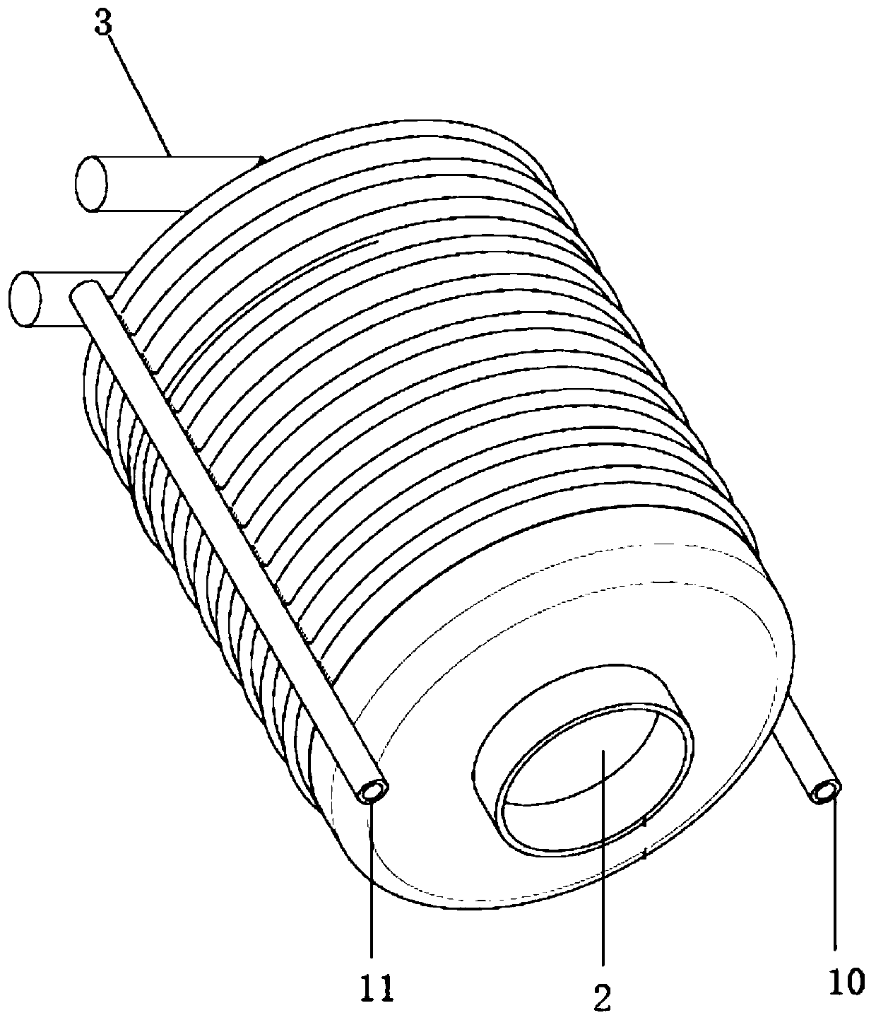
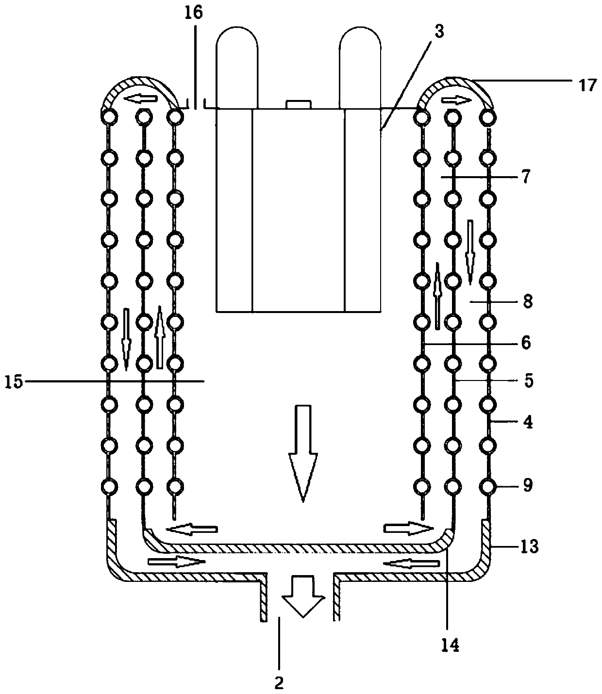
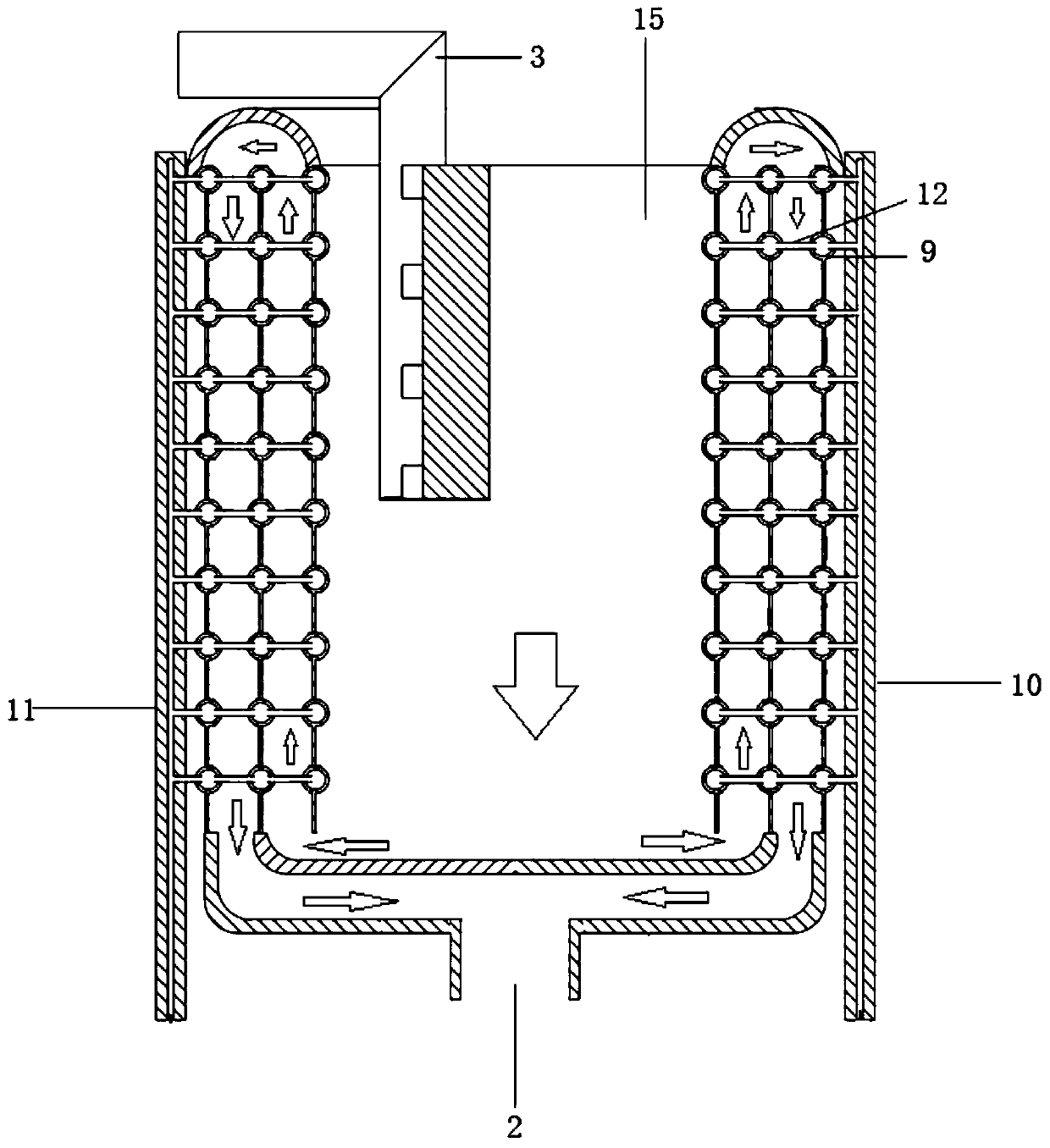
[0048] combined with Figure 1-4 , describe the present invention in detail.
[0049]A heat dissipation device, comprising a cooling chamber, the lower end of the cooling chamber has an outer cylinder support wall 13 and an inner cylinder support wall 14, the outer cylinder support wall 13 extends upwards to form a cylindrical first roundabout wall 4; the inner cylinder supports The wall 14 extends upwards to form the second roundabout wall 5 . The first roundabout wall 4 crosses the second roundabout wall 5 and bends inwardly to form an arc-shaped transition support wall 17. There is a gap between the transition support wall 17 and the second roundabout wall 5, and the transition support wall 17 is parallel to the second roundabout wall. 5 continues to extend to form a third roundabout wall 6 . So far, the cavity wall of the cooling chamber presents a three-return detour wall structure, which are respectively the first detour wall 4 , the second detour wall 5 and the third ...
Embodiment 2
[0116] Embodiment 2, the present invention will be described in detail below in conjunction with the specific installation position of the cooling device in the charging pile box.
[0117] refer to Figure 6 , a charging pile box, including a control area 18, a high-voltage area 20, an air intake and wind direction guiding area 19, and a battery system area 21. The high-voltage area 20 mainly includes a 22V inverter, a transformer, a 24V DC converter, a high-voltage DC copper bar, charger; the air intake and wind direction guide area 19 includes a first set of louvers and a second set of louvers with dust-proof nets; the heat sink is placed in the high voltage area 20 close to the air intake and wind direction guide area 19 position.
PUM
 Abstract
Description
Claims
Application Information
 - R&D
- Intellectual Property
- Life Sciences
- Materials
- Tech Scout
- Unparalleled Data Quality
- Higher Quality Content
- 60% Fewer Hallucinations
Browse by: Latest US Patents, China's latest patents, Technical Efficacy Thesaurus, Application Domain, Technology Topic, Popular Technical Reports.
© 2025 PatSnap. All rights reserved.Legal|Privacy policy|Modern Slavery Act Transparency Statement|Sitemap|About US| Contact US: help@patsnap.com