Working method of double-linkage conveyor discharge valve

A working method and technology of unloading valve, applied in the direction of conveyor objects, transportation and packaging, loading/unloading, etc., can solve problems such as affecting discharge, interfering materials, accumulation, etc., to optimize smoothness, clear material condensation or blockage or stacking effect

Inactive Publication Date: 2018-04-13
CHANGSHA UNIVERSITY OF SCIENCE AND TECHNOLOGY
View PDF1 Cites 2 Cited by
  • Summary
  • Abstract
  • Description
  • Claims
  • Application Information

AI Technical Summary

Problems solved by technology

[0003] In actual use, the existing conveyor unloading valve has the following problems: 1. During the unloading process, there is often a technical requirement for uniform unloading, and the existing technology often requires complex equipment or processes for process control
Therefore, a small part of the prior art uses the technical solution of double-layer unloading, such as CN204573130U, but the design of this valve is just a simple superposition and repetition or mirror image of the opening and closing of the valve, which is just a repetitive design
3. The operating mechanism or driving mechanism of the unloading valve in the prior art often exists in the unloading channel, which will interfere with the flow of materials to a large extent. This field is looking for a certain degree of optimization.
4. The unloading valve of the prior art often causes material condensation or blockage or accumulation, which affects the discharge

Method used


Image

  • Working method of double-linkage conveyor discharge valve
  • Working method of double-linkage conveyor discharge valve
  • Working method of double-linkage conveyor discharge valve

Examples


Embodiment Construction

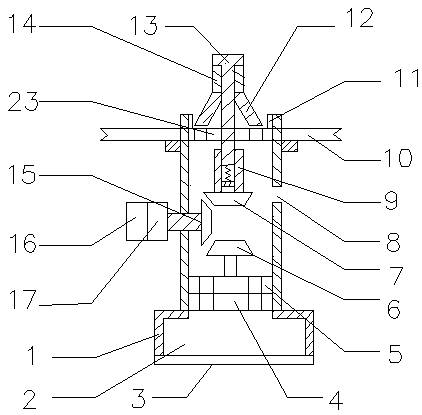
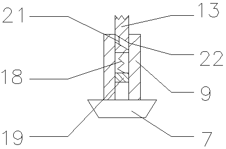
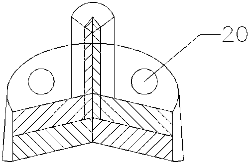
[0022] As shown in the figure: a working method of the unloading valve of a double-linkage conveyor. The unloading valve includes a valve body, a weighing chamber, a weighing plate, a static valve disc, a moving valve disc, a first angular gear, a Angle gear, temperature control port, rod sleeve, limiter, closure, valve stem, pivot rod, third angle gear, motor, reduction mechanism, spring, support disc, through hole, bump, spiral groove, upper valve disc The cross-section of the valve body is inverted T-shaped, the upper part is cylindrical, and the diameter of the lower part is larger than that of the upper part. The lower part of the valve body extends integrally to form a weighing chamber. A pivot is set in the middle of the circle, and the weighing plate can rotate along the pivot; the upper end of the valve body extends inward to form a ring-shaped limiter, which encloses an opening, and the lower surface of the ring-shaped limiter is provided with an upper valve disc, and...


PUM


Abstract

A working method for a double-linkage conveyor unloading valve, the working steps are as follows: the first step is to control the rotation of the motor, drive the third angle gear to rotate through the reduction mechanism, and the third angle gear drives the first and second angle gears to rotate at the same time, The second angle gear drives the valve stem to rise through the rod sleeve, and the valve stem drives the pivot rod and the closure to rise for storage operation, the material hole is opened for discharge, and at the same time, the moving valve disc rotates to the closed position relative to the static valve disc , the weighing cavity is closed; in the second step, after discharging for a predetermined time, the motor is controlled to rotate in reverse, and the closing member is controlled to close the material hole through the transmission structure, and the movable valve disc rotates to the opposite static valve When the disc is opened, the material is dropped into the weighing cavity, and when the material in the weighing cavity reaches a predetermined weight, the first step and the second step are repeated in sequence.

Description

technical field [0001] The invention relates to the related field of conveyor unloading valves, in particular to a working method of a double-linkage conveyor unloading valve. Background technique [0002] In cement, silicate products, new building materials, refractory materials, chemical fertilizers, black and non-ferrous metal beneficiation, and glass ceramics industries, there is a large amount of transportation demand, which is transported to the stockyard or by professional conveyors such as locomotives and cargo ships. Warehouses, where a conveyor discharge valve is required for discharge. [0003] In actual use, the existing conveyor unloading valve has the following problems: 1. During the unloading process, there is often a technical requirement for uniform unloading, and the prior art often requires complex equipment or processes for process control. 2. There is a need in the prior art to improve the reliability of the unloading seal and increase the service life...

Claims


Application Information

Patent Timeline
IPC IPC(8): B65G65/48B65G65/44B65G47/34B65G69/20
CPCB65G65/4818B65G47/34B65G65/44B65G69/20
Inventor 刘鑫王昕宇董建业吴迪尹来容
Owner CHANGSHA UNIVERSITY OF SCIENCE AND TECHNOLOGY
Why Eureka
Try Eureka